This thread has been locked.

If you have a related question, please click the "Ask a related question" button in the top right corner. The newly created question will be automatically linked to this question.

TCA9555: Getting Heating issue after interface with Rotary switch

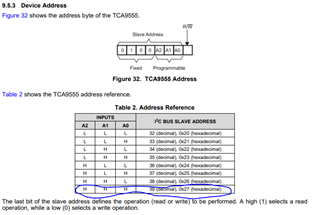
Part Number: TCA9555

Hello, 

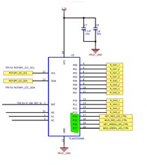
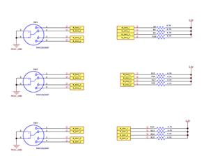
Below is the schematic where IO Expander connected with Rotary switch. 

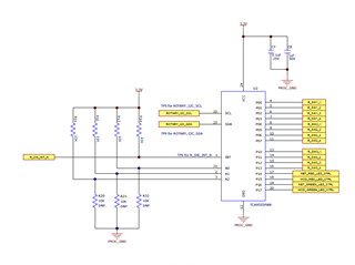
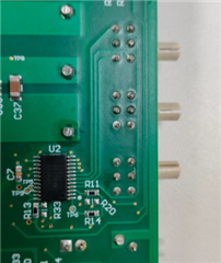
IC is just placed bottom side of PCB board.

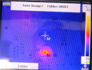
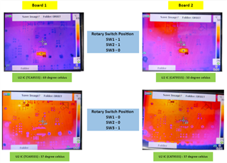
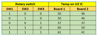
Initially, all rotary switches were on 0's position and temperature was 28 degree C on IC body(Measured by Multimeter). When we changed the setting of rotary switch positions from 0 to 1 then temperature was increasing approx. 10 degree on each changes. W changed the rotary switch position one by one.

When all rotary switches are on 1's position then Temperature was 49 degree C on IC body.

Is this temperature changes bit concern for IC and IC functionality?

Please share your comments and suggestions.

Best regards,

Kiranjit       

  • There is no position "0" in the schematic.

    What are the values of the TCA9555's configuration registers?

  • Hi Clemens,

    There is no position "0" in the schematic

    Below is the image of switch and truth table:

    What are the values of the TCA9555's configuration registers?

    Can you please comment on the temperature issue? Is this heating effect is normal or not? 

    Please share some comments to resolve this issue.

    Thanks,

    Kiran 

  • Hi Kiran,

    In general, the surface temperature of the chip indicates that either the chip is drawing too much current (resulting in excessive heat), or that the chip is operating with a heavy loads. 

    The way to ensure that there is no damage being done to the chip is to take the surface level temperature, and calculate the junction temperature of the device and compare it to the absolute maximum conditions in the datasheet. 

    Absolute maximum junction temperature for the TCA9555 is 100C. Any junction temperature above this, and TI can no longer guarantee device performance, nor guarantee that there wasn't any sustain permanent damage to the device. 

    Where,

    TJ = Junction temperature

    Tc = Maximum case temperature (at the surface of the IC measured at the middle) 

    ψJT = junction-to-top characterization parameter

    Power = total power dissipated by the chip

    From your comment, I don't know the exact power dissipation of the system, but if we were to calculate using maximum conditions, we would come up with

    (TJ(max) - Tc )  /  ψJT  = power(max) 

    (100C - 49C) /  11.1 C/W = 4.595 watts. 

    So the IC in use in your system can dissipate up to 4.595 watts of power at 49C for the TSSOP package without damage to the device. If you draw more power than the calculated value, you risk damaging the IC due to going outside the absolute maximum conditions. 

    My guess is that one of the GPIO pins is configured to an output, and somewhere there is an output driving a high-voltage to GND between the output and the rotary switch. I am assuming that the ON-state resistance of the rotary switch is somewhat small, which acts like a large load to GND. For an input, this is okay, but for an output, this would draw a lot of current to the point that might effect the surface temperature of the IC to the extent you are witnessing. 

    Please look into Clemens' comments about the state of the registers. If you can read the device, what do the registers 0x00 - 0x03 read back from the device? 

    Regards,

    Tyler

  • The slave address appears to be correct. But I do not understand the value 0x8C for the command byte; the only valid values would be 0…7. Please show the code that initializes the TCA9555's registers.

    Like Tyler, I suspect that the pins are configured to output a high signal, which makes a large current flow when the line is shorted to GND externally. Please read the values of all eight registers.

  • Hi Clemens,

    All the pins are configured as inputs at present. The value 0x8C is not clear to me as well, as this is a reference code, but I will try changing it to the address of configuration register and see if there's a difference.

    If I read back the registers, what will they depict?

    How do I display these read values on a terminal window?

    Best Regards,

    Kiran

  • Hi Kiran,

    I agree with Clemens. Slave address looks to be correct with A2/A1/A0 = H, as depicted in the schematic. 

    The 0x8C is not the correct address for the configuration register. To access the configuration register for ports 0 and 1, the command byte needs to be set to 0x06 and 0x07 as described in the datasheet.

    A read of the input port register (0x00 / 0x01) will reflect the incoming logic levels of the pins regardless of whether the pin is defined as an input or output by the configuration register. 

    A read of the output port register (0x02 / 0x03) will reflect the value inside the flip-flop controlling the output selection. Not the actual pin value. 

    A read of the polarity inversion registers (0x04 / 0x05) will show the contents of the polarity inversion registers (default = 0x00). 

    A read of the configuration registers (0x06 / 0x07) will show the contents inside the configuration register telling the user what p-ports are configured as outputs or inputs. If an output, the corresponding bit will read "0", if the corresponding bit is an input, the read will yield "1."

    A read of the configuration register upon power-up without any device configuration should read the value 0xFF, since default state of the p-ports are inputs upon a successful power on reset condition.

    Regards,

    Tyler

  • Please show the code that initializes the TCA9555's registers.

  • Hi Clemens and Tyler,

    Sorry for late response. 

    We were investigating this issue on hardware and firmware level.

    Schematic as follows:

    The Green highlighted port acts as an output port and the remaining act as an input port.

    We have two PCB boards which have the same design. But one board has TCA9555 IO Expander and the other board has CAT9555FYI.

    When we did a thermal analysis of both boards.

    1. TCA9555 IC heated up to 61 degrees.
    2. CAT9555 IC heated up to 41 degrees only.

    Please provide your comments on below points:

    1. Why are we getting temperatures difference between TCA9555 and CAT9555? Although both are using same design?

    2. Is there any specification and/or operational differences between Onsemi (CAT9555) and TI (TCA9555) which could contribute to this heating?

    Best regards,

    Kiran

    3. TCA9555 I2C expanders are capable of supporting both Input and output without heating effect?

  • I'd guess that the TCA9555 has a higher drive strength, so larger currents flow when you short its outputs.

    Please read the values of all eight registers, and show the code that initializes the registers.

  • Hi Clemens,

    Thanks for your response!!

    Below is the thermal profile of TCA9555.

    Attached code: 

    #include "ioc_main.h"
    #include <stdio.h>
    #include <string.h>
    #include <stdbool.h>
    #include <ti/drivers/GPIO.h>
    #include "driverlib/sysctl.h"
    #include <ti/sysbios/knl/Task.h>
    #include <xdc/runtime/System.h>
    #include "ioc_debug.h"
    #include "drivers/i2c/ioc_i2c.h"
    #include "drivers/led/ioc_led.h"
    #include "Board.h"
    #include "../ioc_config.h"
    
    #define LEDONE_SLAVEADDRESS             0x27
    #define LEDTWO_SLAVEADDRESS             0x26
    
    uint8_t ui8TxBuf[3], ui8RxBuf[3];
    
    volatile bool bModuleLedFlag;
    
    /**
     *******************************************************************************
     * @file 		ioc_led.c
     * @ingroup     led
     *
     * @function	StatusLEDConfig()
     *
     * @brief
     *      		This function will be used for configuring digital IO LED's
     * *
     * @param       Null
     *
     * @return      Null
     *
     ******************************************************************************/
    void StatusLEDConfig()
    {
    #if(defined USE_DI && defined USE_DO)
        SysCtlPeripheralEnable(SYSCTL_PERIPH_I2C2);
    
        SysCtlPeripheralEnable(SYSCTL_PERIPH_GPIOP);
        SysCtlPeripheralEnable(SYSCTL_PERIPH_GPION);
    
        GPIOPinConfigure(GPIO_PP5_I2C2SCL);
        GPIOPinConfigure(GPIO_PN4_I2C2SDA);
    
        GPIOPinTypeI2CSCL(GPIO_PORTP_BASE, GPIO_PIN_5);
        GPIOPinTypeI2C(GPIO_PORTN_BASE, GPIO_PIN_4);
    
        I2cStructType stI2cData;
        /* Configuring Digital input LED as Output pins */
        stI2cData.ui32I2cBus = I2C2_BASE;
        stI2cData.i2cSlaveAddress = LEDONE_SLAVEADDRESS;
        stI2cData.ui32TxCount = 3;
        stI2cData.ui32RxCount = 0;
        stI2cData.pui8DataRx = ui8RxBuf;
        ui8TxBuf[0] = 0x06;
        ui8TxBuf[1] = 0x00;
        ui8TxBuf[2] = 0x00;
        stI2cData.pui8DataTx = ui8TxBuf;
        i2cTivaLibTransfer(&stI2cData);
        ui8TxBuf[0] = 0x02;
        ui8TxBuf[1] = 0xFF;
        ui8TxBuf[2] = 0xCF;
        stI2cData.pui8DataTx = ui8TxBuf;
        i2cTivaLibTransfer(&stI2cData);
        SysCtlDelay(1000);
    
        /* Configuring Digital output LED as Output pins */
        stI2cData.ui32I2cBus = I2C2_BASE;
        stI2cData.i2cSlaveAddress = LEDTWO_SLAVEADDRESS;
        stI2cData.ui32TxCount = 3;
        stI2cData.ui32RxCount = 0;
        stI2cData.pui8DataRx = ui8RxBuf;
        ui8TxBuf[0] = 0x06;
        ui8TxBuf[1] = 0x00;
        ui8TxBuf[2] = 0x00;
        stI2cData.pui8DataTx = ui8TxBuf;
        i2cTivaLibTransfer(&stI2cData);
        ui8TxBuf[0] = 0x02;
        ui8TxBuf[1] = 0xFF;
        ui8TxBuf[2] = 0x0F;
        stI2cData.pui8DataTx = ui8TxBuf;
        i2cTivaLibTransfer(&stI2cData);
        SysCtlDelay(1000);
    #endif
    }
    

    #define LED_NETWORKRED                  0x0110
    #define LED_NETWORKGREEN                0x0120
    #define LED_NETWORKAMBER                0x0130
    
    #define LED_MODULERED                   0x0140
    #define LED_MODULEGREEN                 0x0180
    #define LED_MODULEAMBER                 0x01C0
    
    /*#define MOD_RED     0x40
    #define MOD_GREEN   0x80
    #define MOD_AMBER   0xC0
    
    #define NET_RED     0x10
    #define NET_GREEN   0x20
    #define NET_AMBER   0x30
    */
    
    #define MOD_RED     0x20
    #define MOD_GREEN   0x80
    #define MOD_AMBER   0xA0
    
    #define NET_RED     0x10
    #define NET_GREEN   0x40
    #define NET_AMBER   0x50
    
    #define DI_LED_SLAVEADDRESS             0x27
    #define DO_LED_SLAVEADDRESS             0x26
    
    #define CONFIG_DIGITALINPUTLED          0xF000
    #define CONFIG_DIGITALOUTPUTLED         0xFFFF


    /* LED Configuration data Marcos */
    #define LED_CONFIG_COMMANDBYTE         0xBC
    #define LED_CONFIG_DATAVALUE                   0x00
    #define LED_SLAVEADDRESS                       0x27
    #define LED_CONFIG_WRITECOUNT          4
    #define LED_CONFIG_READCOUNT           0
    
    /* LED Output Register/ Status Read Data Macros */
    #define LED_OUTPUTREG_COMMANDBYTE             0x84
    #define LED_UPDATE_WRITECOUNT           1
    #define LED_UPDATE_READCOUNT            3
    

    Please go through above information and let me know if you need anything else.

    Thanks in advance.

    Best regards,

    Kiran

  • Apparently, the code confuses the output port registers (2,3) and the configuration registers (6,7).

        stI2cData.pui8DataRx = ui8RxBuf;
        ui8TxBuf[0] = 0x06;
        ui8TxBuf[1] = 0x00;
        ui8TxBuf[2] = 0x00;
        stI2cData.pui8DataTx = ui8TxBuf;
        i2cTivaLibTransfer(&stI2cData);

    This configures all sixteen pins as outputs. But the pins that you want to be inputs must be configured with 1 bits:

        ui8TxBuf[0] = 0x06;
        ui8TxBuf[1] = 0xFF;
        ui8TxBuf[2] = 0x0F;

    (The symbols in the second file are not actually used. You should clean them up.)

  • Hi Clemens,

    Sorry for the earlier code snippet it was used in the reference, please find the below code snippet for the initial configuration which is being used currently 


    #define ROTARY_CONFIG_COMMANDBYTE       0x06
    #define ROTARY_CONFIG_DATAVALUE         0xFF
    
    #define ROTARY_SLAVEADDRESS				0x27
    #define ROTARY_I2CBUS                   1
    #define ROTARY_CONFIG_WRITECOUNT        3
    #define ROTARY_CONFIG_READCOUNT         0
    
    /* Rotary Input register Data Macros */
    #define ROTARY_INPUTREG_COMMANDBYTE 	0x00
    #define ROTARY_INPUTREG_WRITECOUNT		1
    #define ROTARY_INPUTREG_READCOUNT    	2
    

    void ioc_RotaryWriteConfiguration()
    {
    	i2cConfigbus stI2cConfig;
        uint8_t aui8TxBuffer[ROTARY_CONFIG_WRITECOUNT];
        uint8_t aui8RxBuffer[ROTARY_CONFIG_READCOUNT];
    
        aui8TxBuffer[0] = ROTARY_CONFIG_COMMANDBYTE;
        aui8TxBuffer[1] = ROTARY_CONFIG_DATAVALUE;
        aui8TxBuffer[2] = 0x0F;
    
    	stI2cConfig.pui8txbuffer = aui8TxBuffer;
    	stI2cConfig.vui8I2cBus = Board_I2C1;
    	stI2cConfig.vui8writeCount = ROTARY_CONFIG_WRITECOUNT;
    	stI2cConfig.vui8readCount  = ROTARY_CONFIG_READCOUNT;
    	stI2cConfig.pui8RxBuffer = aui8RxBuffer;
    	stI2cConfig.vui8slaveAddress = ROTARY_SLAVEADDRESS;
    
    	ioc_I2cWrite(&stI2cConfig);
    }

    Please share your comments/suggestions.

    Best Regards,

    Kiranjit

  • This code looks correct.

    But to be safe, please read back all eight registers.

  • Hi Clemens,

    I will read back the internal registers but where /how do I print the value being read?

    Best Regards,

    Kiranjit

  • Hi Kiranjit,

    In the coding IDE, can you store the read value inside a variable or int and then read that storage container inside the IDE? 

    Also this thread is going in different directions. 

    To address the issue concerning the 61C, this is still underneath the TA temperature. As long as ICC current or maximum output current through the GPIO's is being respected, then this temperature is okay for the device. Main thing to keep in check is the current consumption, and that it doesn't exceed abs. max conditions. 

    TCA9555 compared to the CAT9555 device from ONSEMI might just be output strength differences, die differences, there really is no one clear answer to why the current consumptions are different other than they are different parts with different designs, with similar functionality. 

    Is the temperature of the TCA9555 chip affecting your system in a negative way, or are you just curious for a reason why the temperature is higher than the ONSEMI part? 

    Regards,

    Tyler

  • Hi Tyler,

    Thanks for your response.

    In the coding IDE, can you store the read value inside a variable or int and then read that storage container inside the IDE? 

    I will try.

    Is the temperature of the TCA9555 chip affecting your system in a negative way, or are you just curious for a reason why the temperature is higher than the ONSEMI part? 

    >> If it continuously works on higher temperature then it may degrade the life of IC and functionality.

    Below is the temp. variation on IC with respect to position of rotary switch. (Schematic already shared in question itself.)

    Both boards have same design, only has different IO Expander IC.

    Please share your comments to identify the root cause of this heating issue.

    Best Regards,

    Kiranjit 

  • Hi Kiranjit,

    There is no exact way for me to isolate the root cause of this heating issue. It may be that the silicon of the CAT9555 is better designed, and has better heat dissipation than the TCA9555. If this issue was of a concern across two TCA9555 devices that were of the same silicon but resulted in different IC temperature, then I would be curious to know why this is happening. 

    Because it involves two chips from two different manufacturers, I not sure what could be the result of the heating other than that the CAT9555 might be a better design for heat dissipation. 

    Just a quick look at the abs. max specs of both datasheets. CAT9555 is rated for 150C, and TCA9555 is rated for 100C abs. max. Just off of this, I am sure there are major internal differences between the two devices that would cause the abs. max junction temp to be 50C > than the TI device. 

    My only suggestion is to use a switch that has a weaker load. It seems the rotary switch is drawing too much current in certain positions. 

    Regards,

    Tyler