This thread has been locked.

If you have a related question, please click the "Ask a related question" button in the top right corner. The newly created question will be automatically linked to this question.

DS90UB925Q-Q1: How to set the LFMODE over register settings

Part Number: DS90UB925Q-Q1

Hi,

I am using the DS90UB925Q-Q1 for serializing RGB888. Raspberry pi generates the RGB888 signal as the source.

because of the low pixel clock 12Mhz I want to use the LFMODE.

By the Hardware which I am using for this Task, I modified the MODE_SEL to get the LFMODE, unfortunately, I cannot set the counterpart DS90UB926 to LFMODE from the register settings.

The 12 Mhz is chosen because the real Hardware has only 12Mhz.

Thanks in advance for support

Mesut
The register settings :

Ret 0x00 = 0x58 1011000
Ret 0x01 = 0x04 100
Ret 0x02 = 0x03 11
Ret 0x03 = 0xF0 11110000
Ret 0x04 = 0xFE 11111110
Ret 0x05 = 0x1E 11110
Ret 0x07 = 0x18 11000
Ret 0x19 = 0x01 1
Ret 0x1C = 0x02 10
Ret 0x1D = 0xA0 10100000
Ret 0x23 = 0x10 10000
Ret 0x26 = 0x83 10000011
Ret 0x27 = 0x84 10000100
Ret 0x32 = 0x10 10000
Ret 0x33 = 0x25 100101
Ret 0x34 = 0xFA 11111010
Ret 0x3B = 0x01 1
Ret 0x3D = 0xA0 10100000
Ret 0x3F = 0x10 10000
Ret 0x40 = 0x43 1000011
Ret 0x41 = 0x03 11
Ret 0x42 = 0x03 11
Ret 0x44 = 0x30 110000
Ret 0x45 = 0x70 1110000
Ret 0x48 = 0x0F 1111
Ret 0x50 = 0x03 11
Ret 0x51 = 0x10 10000
Ret 0x53 = 0x01 1
Ret 0x54 = 0x80 10000000
Ret 0x56 = 0x08 1000
Ret 0x59 = 0x3F 111111
Ret 0x5A = 0x20 100000
Ret 0x5B = 0x20 100000
Ret 0x64 = 0x10 10000
Ret 0x73 = 0x07 111
Ret 0x74 = 0x07 111
Ret 0x75 = 0x08 1000
Ret 0x7C = 0x02 10
Ret 0xC8 = 0x40 1000000
Ret 0xF0 = 0x5F 1011111
Ret 0xF1 = 0x55 1010101
Ret 0xF2 = 0x42 1000010
Ret 0xF3 = 0x39 111001
Ret 0xF4 = 0x32 110010
Ret 0xF5 = 0x36 110110
Device name : _UB926


Ret 0x00 = 0x18 11000
Ret 0x03 = 0xD2 11010010
Ret 0x04 = 0x83 10000011
Ret 0x0C = 0x05 101
Ret 0x0D = 0xA0 10100000
Ret 0x13 = 0x18 11000
Ret 0x16 = 0xFE 11111110
Ret 0x17 = 0x5E 1011110
Ret 0x18 = 0xA1 10100001
Ret 0x19 = 0xA5 10100101
Ret 0x22 = 0x25 100101
Ret 0x29 = 0x24 100100
Ret 0x2B = 0xA0 10100000
Ret 0x30 = 0x03 11
Ret 0x31 = 0x10 10000
Ret 0x36 = 0x08 1000
Ret 0x37 = 0x34 110100
Ret 0x39 = 0x0A 1010
Ret 0x3A = 0x20 100000
Ret 0x3B = 0x21 100001
Ret 0x3E = 0xF0 11110000
Ret 0x50 = 0x26 100110
Ret 0x64 = 0x10 10000
Ret 0xC2 = 0x80 10000000
Ret 0xC4 = 0x58 1011000
Ret 0xC7 = 0x60 1100000
Ret 0xC8 = 0x40 1000000
Ret 0xF0 = 0x5F 1011111
Ret 0xF1 = 0x55 1010101
Ret 0xF2 = 0x42 1000010
Ret 0xF3 = 0x39 111001
Ret 0xF4 = 0x32 110010
Ret 0xF5 = 0x35 110101
Device name : _UB925

  • Mesut,

    Are you connecting directly to the 926 local I2C or trying to program this through the FPD-Link?

    To set through registers I recommend to program 0x02 = 0x03 and then issue a digital reset through 0x01 = 0x01

    Best Regards,

    Casey 

  • Casey,
    thanks for the fast response yes is connected directly and also used the reset over the 0x1 register.
    The values are after the reset Ret 0x02 = 0x03 11


    kind regards
    Mesut

  • Hello Mesut,

    Ok that seems like the correct setting - are you having an issue? Can you describe exactly what your issue is and your test setup?

    Best Regards,

    Casey 

  • Hello Casey,
    I am using the DS90UB925QSEVB for controlling the Chip.
    Before I had switched to LFMODE on UB925 I could get a lock with high frequency configured on raspberry pi.
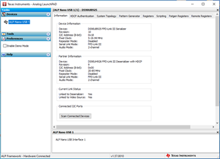
    By the screenshot, you can see that the UB926 is not in LFMODE and I am also not getting lock.

    kind regards
    Mesut


  • Mesut,

    I don't see an immediate issue which stands out here. If you use the physical MODE strap to set LFMODE on the 926, then does the link work as expected? Only the register override specifically is not working? 

    Can you share any more data here such as the clock waveform, the cable type/length, or the schematics for review?

    Best Regards,

    Casey 

  • Hi Casey,

    The part with 926 is a separate Hardware  "Framegraber"  which is working in normal mode. But unfortunately, the  MODE_SEL is connected to the ground and it is not so easy to remove.
    Could this be the Issue why is it not going to LFMODE because in the datasheet 40.2 Ohms are used? 

    The Cable which I am using works in non-LFMODE and is only  35cm Long FAKRA HSD LVDS 


    Best Regards,
    Mesut

  • Hello Mesut,

    I'm not certain at the moment but I believe that the way you are overriding the LFMODE should work. Can you please also provide scope shots of the clock input to 925 with the low frequency PCLK rate?

    Best Regards,

    Casey 

  • Hi Casey,
    These are the PCLK and DE waveforms.


    Best Regards
    Mesut


  • Hi Mesut,

    Just to confirm understanding, can you share the full register override script you are attempting to use?

    I want to confirm there isn’t any accidental resets clearing the overrides, etc. 

    Regards,

    Logan

  • Hi Logan,
    I was able to set the register after several tries with this python script.

    Now I have both in LFMODE but still not get the lock.
    Do you have a pseudo code for Initialisation in LFMODE  .

    kind regards

    Mesut

    UB926 side

    I2CBUS1.write_byte_data(0x2C, 0x02, 0x03)
    I2CBUS1.write_byte_data(0x2C, 0x02, 0x03)
    time.sleep(1)

    I2CBUS1.write_byte_data(0x2C, 0x01, 0x01)

    ---------------------------------------
    Reg 0x00 = 0x58 1011000
    Reg 0x02 = 0x03 11
    Reg 0x03 = 0xF0 11110000
    Reg 0x04 = 0xFE 11111110
    Reg 0x05 = 0x1E 11110
    Reg 0x07 = 0x18 11000
    Reg 0x19 = 0x01 1
    Reg 0x1C = 0x02 10
    Reg 0x1D = 0xA0 10100000
    Reg 0x23 = 0x10 10000
    Reg 0x26 = 0x83 10000011
    Reg 0x27 = 0x84 10000100
    Reg 0x32 = 0x10 10000
    Reg 0x33 = 0x25 100101
    Reg 0x34 = 0xFA 11111010
    Reg 0x3B = 0x0F 1111
    Reg 0x3D = 0xA0 10100000
    Reg 0x3F = 0x10 10000
    Reg 0x40 = 0x43 1000011
    Reg 0x41 = 0x03 11
    Reg 0x42 = 0x03 11
    Reg 0x44 = 0x30 110000
    Reg 0x45 = 0x70 1110000
    Reg 0x48 = 0x0F 1111
    Reg 0x50 = 0x03 11
    Reg 0x51 = 0x10 10000
    Reg 0x53 = 0x01 1
    Reg 0x54 = 0x80 10000000
    Reg 0x56 = 0x08 1000
    Reg 0x59 = 0x3F 111111
    Reg 0x5A = 0x20 100000
    Reg 0x5B = 0x20 100000
    Reg 0x64 = 0x10 10000
    Reg 0x73 = 0x07 111
    Reg 0x74 = 0x07 111
    Reg 0x75 = 0x08 1000
    Reg 0x7C = 0x02 10
    Reg 0xC8 = 0x40 1000000
    Reg 0xF0 = 0x5F 1011111
    Reg 0xF1 = 0x55 1010101
    Reg 0xF2 = 0x42 1000010
    Reg 0xF3 = 0x39 111001
    Reg 0xF4 = 0x32 110010
    Reg 0xF5 = 0x36 110110
    Device name : _UB926
    --------------------------------------------
    Ret 0x00 = 0x18 11000
    Ret 0x03 = 0xD2 11010010
    Ret 0x04 = 0x83 10000011
    Ret 0x0C = 0x04 100
    Ret 0x0D = 0xA0 10100000
    Ret 0x13 = 0x18 11000
    Ret 0x16 = 0xFE 11111110
    Ret 0x17 = 0x5E 1011110
    Ret 0x18 = 0xA1 10100001
    Ret 0x19 = 0xA5 10100101
    Ret 0x22 = 0x25 100101
    Ret 0x29 = 0x24 100100
    Ret 0x2B = 0xA0 10100000
    Ret 0x30 = 0x03 11
    Ret 0x31 = 0x10 10000
    Ret 0x36 = 0x08 1000
    Ret 0x37 = 0x34 110100
    Ret 0x39 = 0x0A 1010
    Ret 0x3A = 0x20 100000
    Ret 0x3B = 0x21 100001
    Ret 0x3E = 0xF0 11110000
    Ret 0x50 = 0x26 100110
    Ret 0x64 = 0x10 10000
    Ret 0xC2 = 0x80 10000000
    Ret 0xC4 = 0x10 10000
    Ret 0xC7 = 0x60 1100000
    Ret 0xC8 = 0x40 1000000
    Ret 0xF0 = 0x5F 1011111
    Ret 0xF1 = 0x55 1010101
    Ret 0xF2 = 0x42 1000010
    Ret 0xF3 = 0x39 111001
    Ret 0xF4 = 0x32 110010
    Ret 0xF5 = 0x35 110101
    Device name : _UB925


  • Mesut,

    The clock waveform from your previous post looks very distorted and the duty cycle is changing by large amounts. Are you able to get a jitter measurement from the clock to compare against the datasheet limits? You can use this guide to measure the jitter at TP1 with a scope jitter analysis tool like DPOJET. 

    92x-91x Jitter_measurment_Feb2023.pdf

    It seems to me like the clock input might be highly distorted which is causing the link not to be able to lock since the 925 uses the input PCLK to drive the FPD-Link channel. 

    Best Regards,

    Casey