This thread has been locked.

If you have a related question, please click the "Ask a related question" button in the top right corner. The newly created question will be automatically linked to this question.

ONET1151L: What factors contribute to the optical jitter observed on a TOSA output

Part Number: ONET1151L

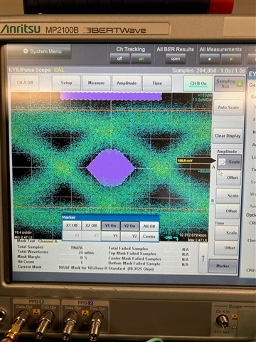
I have a laser driver / TOSA combination and I am using an optical scope to look at the eye diagram for the TOSA output. I am getting an eye, but the lines defining the eye are very thick and I am getting an unacceptable BER (using an Anritsu MT-1000 analyzer). The question is, what are sources of the jitter that I am observing? Is it a termination issue? Is it settings of the laser driver? Is it layout? Is it all of the above?

I am looking for a methodical way to determine the specific problem so I can isolate and fix it. If you have any suggestions for diagnosing this issue please let me know.

Thank you,

Michael

  • One additional question... The layout recommendations say to make the connection between the laser drive and the TOSA to be "as short as possible". Is there a distance between the two that you should not exceed? I am talking about 10Gbs operation here.

    Thank you,

    Mike Nycz 

  • Hi Michael,

    First we should run experiments or capture scope shots to see if this issue is related to the laser driver/system side or the TOSA assembly. 

    Secondly, also we should monitor input of the laser driver - ONET1151L - to see if this is occuring on the system side or perhaps laser driver interface to the TOSA side.

    Once we determine which segment of the application is causing this issue, then we a more clear picture of where we need to concentrate on and what are the potential root causes.

    Regards,Nasser

  • Hello Nasser,

                  Here is the eye diagram that I recorded at the output of the TOSA.

    To generate the EYE I am using an MT-1000 ethernet tester in single port mode. The port is connected to a test board. This same test board is used for other designs and we see near perfect eye diagrams for these other designs. Therefore we concluding that the test setup is not in question.

    The test board is connected to the LD/TOSA and LA/ROSA on our circuit board. The optical output (TOSA) is split. One output goes to the Bertwave for the eye. The other goes back into the ROSA on our circuit board which completes the loop for the MT-1000 tester.

    You can see the results above. The setup does pass data. However, the BER rates are in the E-5 range which is unacceptable.

  • Hi Michael,

    Agreed something in the link does not seem to have been tuned - based on your scope shot. I am wondering if you can run the same test but at a lower data rate. Then use a differential high impedance scope probe and check signal along the signal path. I believe this could tell us where along the link we need to do further fine tuning.

    Regards, Nasser