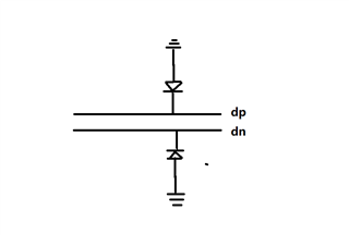
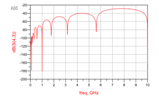
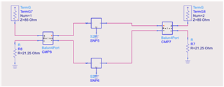
The ESD device is connected to the circuit in parallel, as shown in Figure 1. When ADS is used to simulate IL, circuit diagram 2 is built in parallel mode, and the simulated IL is shown in Figure 3. On the contrary, the circuit is built in series mode, as shown in Figure 4, and the simulation results seem to be correct, as shown in Figure 5.
Question 1: Help to see which way of constructing simulation crosstalk and the result is correct.
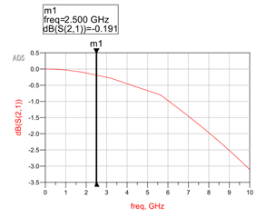
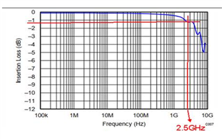
Question 2: The result in Figure 5 is about 0.2, while the value given by the specification is relatively large, as shown in Figure 6, about 1db, which should prevail
(The simulation model is downloaded from TI's official website)