This thread has been locked.

If you have a related question, please click the "Ask a related question" button in the top right corner. The newly created question will be automatically linked to this question.

DS90UB935-Q1: Do we need to do initial setting for SerDes?

Part Number: DS90UB935-Q1

Hi team,

As I know that we don't need to do initial setting register of 935 and 936 that SerDes will connect by themselves. However, My customer would like to know the reason about why SerDes don't need it? Would you please help to explain it for me that I can discuss with customer? thanks!

BR,

Jimmy 

  • Hi Jimmy,

    The customer has to strap the correct Mode Select settings, for their application, on the 935 & 936. These FPD-Link devices work in synchronous mode by having the SER lock to the back channel of DES. Based on the back channel, the SER will generate a forward channel which the DES will then lock too.

    Based on customer use cases it is necessary to configure the SerDes registers to fit the needs of the system it is being implemented in. For example, it may be important for the customer to configure registers that deal with CSI-2 settings, frame sync settings, target IDs and aliases, etc.

    I hope this helps answer your question.

    Best regards,

    Anthony

  • Hi Anthony,

    I discuss with customer today and got the point why they asked this question.

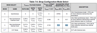
    at the old version image sensor module don't have oscillator. 935 Mode Pin is using RH / RL = 71.5k / 56.2k non-sync internal clock mode as below picture. 

    then will change registration configuration to write value 58 in Reg address 0x03. 58(DEC) = 00111010(BIN)

    At this old version situation. Display fine. Hot swap fine.

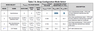
    However the new one we use sync mode. Mode Pin is using RH / RL = OPEN / 10k Sync mode as blow.

    We only change resistor at Mode Pin to sync mode. at first time the display is fine. but when we test hot swap(unplug image sensor then connect back) there will be no display. Would you have any idea about this situation? should we need to change registration configuration again? if yes, what kind of value we should use?

    BR,

    Jimmy

  • Hi Jimmy,

    Can you confirm if the modes on the 935 & 936 are the same? For example, when the 935 is strapped to sync mode is the 936 also strapped to sync mode.

    Best regards,

    Anthony

  • Hi Anthony,

    Yes, the mode on the 935 and 936 are the same sync mode. 936's software and hardware also set to sync mode. 

    BR,

    Jimmy

  • Hi Jimmy,

    Can you provide me with register dumps of pre and post hot swap 935 & 936? Also, I want to make sure that the customer understands in order to change mode select settings they need to have the mode select circuit & register configured correctly.

    Looking forward to your response,

    Anthony

  • Hi Anthony,

    I asked customer to list the hardware and software setting as below.

    At non-sync mode display work fine. Hot swap also work fine. However, when we re-connect image sensor will have no display issue at sync mode.

           1.Make sure sync mode hardware setting.

      1. As we talked last time we only change 935 mode pin to sync mode. 935: Mode Pin is using RH / RL = OPEN / 10k Sync mode
      2. How about the 936 setting? 936: Mode Pin is using?

            2.Check sync mode software setting.

      1. Would you please provide me with register dumps of pre and post hot swap 935 & 936? BU can check the register by those file to notice where might have the problem.
      2. About setting the software. Which register is re-wrote and what kind of value is wrote in? As I know at non-sync mode is address 0x03 to 58(DEC)

    As 2. b. question. I would like to know if I would like to change from non-sync mode to sync mode, which register we need to change? and what is the value?

    BR,

    Jimmy

  • Hi Jimmy,

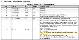
    For sync mode, the 935 mode pin should be strapped to sync mode. In order to confirm you are in sync mode you can read back register 0x03. Bits 0-2 will indicate what mode you are in. For the 936 mode pin you need to strap to sync mode as well. In order to confirm you are in sync mode you can read back register 0x58. Bits 0-2 will indicate what mode you are in (mode is based on back channel rate). 

    935 register 0x03 below: 

    936 register 0x58 below:

    To be in sync mode, register 0x03 on the 935 needs to be strapped & set to 0x00. For the 936, register 0x58 needs to be strapped & set to 0x5E.

    If the above information is able to resolve your issue then awesome! If not, being provided register dumps of the 935 & 936 pre and post hot swap would allow me to see in greater detail what is going on in our devices.

    Best regards,

    Anthony

  • Hi Anthony,

    Thanks for your information.

    Just would like to check that do our 935/936 support hot swap at image sensor side? 

    BR,

    Jimmy

  • Hi Jimmy,

    What is the customer's purpose for doing hot swap testing? This is not recommended outside of testing purposes.

    Best regards,

    Anthony