This thread has been locked.

If you have a related question, please click the "Ask a related question" button in the top right corner. The newly created question will be automatically linked to this question.

TCAN3414: About the TCAN3414 PCB layout question

Part Number: TCAN3414

hello 

I have some questions about the TCAN3414 PCB layout,i think all the CAN TR ICs are similar, so Take this chip for example.

1. About the Common Mode Inductor Location 

Where should I put the common mode inductor is the optimal solution? Placed close to the connector or place close to the CAN IC ? 

I prefer to place it close to the IC, The way I understand the role of the CM inductor is that reduce the RE,CE energy,So being close to the IC can eliminate interference at the source, What's your idea?

2.  Where is the best place to put the terminating resistor?(R2,R3 of the following picture)

Does the location of the terminating resistor have any effect on the circuit?

if i change the terminating resistor to this loclation, is there any issue ? 

please give me some advice about the above questions.

Thank you 

Best regards 

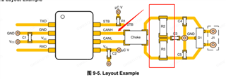
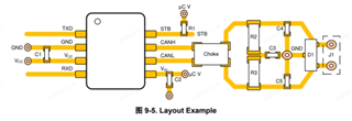
this picture comes from the TCAN3414 datasheet:

  • Hi Qinlei,

    Thanks for sharing your question with us on E2E!

    1. About the Common Mode Inductor Location 

    Optimal placement for the CMC is close to the transceiver IC with no components in between. The CMC will filter any common code noise that is generated by the transition of the CAN signal by the transceiver. This noise should be filtered as soon as possible so that it does not have a chance to propagate into other parts of the system. Therefore a short distance between the transceiver and this filter component is ideal. 

    2.  Where is the best place to put the terminating resistor?(R2,R3 of the following picture)

    This placement is less critical, but it is common to place termination resistors near the transceiver IC as well (on the connector-side of the CMC). This is mainly to reduce the "stub" that is formed by the traces from the termination to the CAN IC when the signal is originating from another node. Because there is tolerance in many designs for longer stubs (up to a few meters), there is certainly tolerance to place these components slightly further away on the same PCB - but ideal placement would still keep them close. 

    Keep in mind that optimal CAN routing will use the shortest distance between the CAN IC and the connector, so all of these should be placed as close to the connector as feasible. When this is done, all bus components will naturally be placed optimally near the IC (CMC + termination) or connector (protection circuit). 

    Let me know if you have any more questions. 

    Regards, 
    Eric Schott