This thread has been locked.

If you have a related question, please click the "Ask a related question" button in the top right corner. The newly created question will be automatically linked to this question.

TCAN1044A-Q1: GT/B 41588.2-2022/ISO 11898-2:2016 ?

Part Number: TCAN1044A-Q1

hi teams:

Could you please help confirm the following questions?

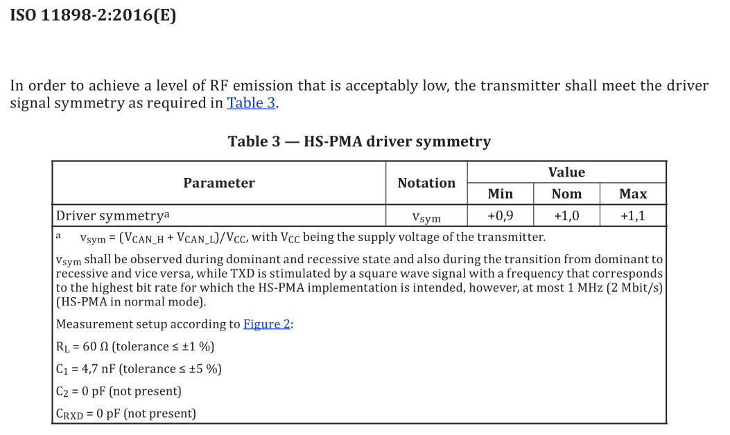
The voltage symmetry issue in CAN chip testing is as follows:

According to the national standard GT/B 41588.2-2022/ISO 11898-2:2016

Vsym=(VCAN-H+VCAN_L)/Vcc, VSYM standard is 0.9-1.1

Test image waveform 2 green indicates CAN_ H. Waveform 3, blue represents CAN_ L. Waveform MATH purple as CAN_ Com (CAN_H+CAN_L)

Due to Vcc being 5V, VSYM=(Min=0.878, Max=1.092) can be calculated based on the waveform, which does not meet the standard.

  • Hi Kevin,

    Thanks for sharing these test results with us on E2E. 

    We validate all of our CAN devices through third party compliance test housed that ensure our transceivers meet the ISO 11898-2 CAN physical layer standard. These test houses create specialized boards to evaluate our transceivers to ensure there is minimal influence on performance based on PCB design or layout. Vsym is one such parameter that is quite sensitive to board characteristics because it so heavily relies on the similarity of the CANH and CANL signals. For instance, any mismatch in the capacitance of these signal traces can cause one to hold more charge in the dominant state than the other and therefore have more influence on the passive dominant-to-recessive transition than the other signal line - influencing the resulting Vsym measurement. 

    To ensure you are not receiving any excess error from the test setup, I would advise zooming in further in time and voltage scales on the oscilloscope to show just the transition of the signals. I would also recommend removing the TVS diode and any external connections from the board to ensure you are evaluating the behavior of the transceiver itself as much as possible. 

    Let me know if you have any further questions or find other results that conflict with our datasheet description and I can help resolve any concerns. 

    Regards, 
    Eric Schott 

  • hi Eric:

    The customer wants to know if TCAN1044A-Q1 has passed the test report of GT/B 41588.2-2022/ISO 11898-2:2016

  • Hi Kevin,

    We have passing test results for the North American compliance test J2962, the European EMC compliance test from Zwickau, and the international interoperability test from C&S. All of these tests are run by third parties and use the ISO 11898-2 CAN standard to define the requirements for their evaluation. Because of this and the fact that the transceiver was designed to meet this standard, we maintain that TCAN1044A is compliant to the ISO 11898-2 physical layer CAN standard. 

    All of these reports are available to share with the customer and can be found on the trx/ sharepoint under the relevant device folder. Let me know if there are any questions regarding the information included in the reports. 

    Regards, 
    Eric Schott 

  • hi Eric:

    All of these reports are available to share with the customer and can be found on the trx/ sharepoint under the relevant device folder. Let me know if there are any questions regarding the information included in the reports. 

           Can you provide this report?

  • Hi Kevin,

    Which report would you like me to send? J2962, C&S, or Zwickau? For the Vsym parameter, C&S will likely be the most relevant. 

    Please send me an email directly requesting this information and I can forward it to you. You can find my contact info by clicking on my E2E name. Alternatively you may give me permission here and I'll send the report to the email you have associated with your E2E account. 

    Regards,
    Eric Schott

  • hi  Eric

    i have send the report to the customer, but customer follow your suggestion , remove the TVS diode and any external connections from the board ,but the test result of Vsym can't meet with ISO 11898-2:2016, could you help review this case again. 

  • Hi Colt,

    Is is possible to share the scope shots with a finer zoom on the dominant-to-recessive transition? I'm curious to see the CAN signals in detail during this transition and am interested to see if the finer time scale lowers the measure voltage on the differential.

    Regards, 
    Eric Schott 

  • Copying the scope shots from the other thread here:

  • Hi Colt,

    Thanks for sharing the scope shots here. I  have unlocked this thread so we may continue our conversation here. 

    It appears that the falling edge of the CAN signals is not symmetrical. This is mostly a passive transition where the CAN driver goes from an active dominant state to a passive (higher impedance) recessive state. This means that the transceiver only has a small influence on the shape of this edge where system conditions can have a much greater impact. 

    In this case it looks like the CANH signal has a longer fall time than CANL. This is most often caused by an asymmetrical load on the CAN signal. This can be the result of signal routing, passive components, solder imperfections, board defects, or other characteristics of the CAN system as a whole. Is it possible to share the layout of the CAN signal on the board you are testing with? I would like to review this for any characteristics that may impact the common mode signal during this transition. If this information is considered confidential, you may share it to me directly through email as opposed to this public forum. You can find my contact information by clicking on my E2E name. 

    Regards, 
    Eric Schott