


Part Number: SN65HVD07
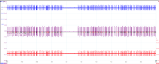
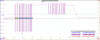
Per the request of TI Rep: Donjie Billy Hipolito. There is an issue on the B but not A where the voltage drops and then crashes the SN65HVD07. The driver needs to be reset to resolve the modbus issue.
Part Number: SN65HVD07
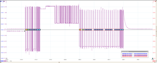
Per the request of TI Rep: Donjie Billy Hipolito. There is an issue on the B but not A where the voltage drops and then crashes the SN65HVD07. The driver needs to be reset to resolve the modbus issue.

