This thread has been locked.

If you have a related question, please click the "Ask a related question" button in the top right corner. The newly created question will be automatically linked to this question.

THVD2410: Second source part for MAX3440EESA+

Part Number: THVD2410

Hi 

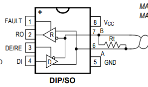
I am looking for a second source part for MAX3440EESA+ RS-485 transceiver. I searched using "Cross-reference" search in TI website. THVD2410DR is listed as the alternate part and that is it a pin for pin replacement. But, the pin-out doesn't seem to match. Please find attached pinout of MAX3440EESA+. It is different from that of THVD2410DR . Can you please clarify. 

Best Regards

Datta

  • Hi Datta,

    It seems we may have a typo in the cross reference tool. The THVD2410DR is the closest functionally to the  MAX3440EESA+ - but they are not pin to pin. So it doesn't seem we have a good second source for this use case. I have provided a bit more information below - but if you need pin to pin for a second source we don't have a good one as the "fault" indication pin is more uncommon on RS-485 devices and we currently don't support any devices with that feature. 

    We don't have an RS-485 transceiver with a fault output pin as shown - while devices like THVD2410 are fault protected in very similar ways the transceiver itself cannot tell when a fault has happened. 

    The THVD2410:

    1. Has receiver failsafe - so if the A/B pins are shorted, left opened, or left in an idle state the "R" output pin will go high (same as MAX device) 

    2. Has A/B bus fault protection of +/-70V which actually does exceed the MAX device. 

    3. Our device has a larger effective common mode range (+/-25V) - but will the transceiver will not state when it is out of these bounds - but if you are using in a system with MAX device your common mode range is only -7V to 12V so our device will remain operational at higher common mode voltages. 

    The big difference is that:

    1. We don't have the fault pin - if you must know when a fault has occurred additional circuitry would need to be added. 

    2. Our "R" (RO) pin is pin 1 - the MAX device is on 2. 

    3. We separate the enables - but if you short the /RE and DE pins together they will act the same as the MAX device. 

    Essentially - this is the closest electrically and functionally you will get from us - but it isn't a direct replacement and most likely not a good option for a second source. 

    Please let me know if you have any other questions and I will see what I can do!

    Best,

    Parker Dodson