This thread has been locked.

If you have a related question, please click the "Ask a related question" button in the top right corner. The newly created question will be automatically linked to this question.

DS90UB941AS-Q1: Using a Qualcomm based (Quectel SMART-EVB-G2_V1.3 (with SC668S-EM) that outputs MIPI DSI siganl

Part Number: DS90UB941AS-Q1
Other Parts Discussed in Thread: DS90UB926Q-Q1, MIDAS

Hello

    • We are trying to use the MIPI DSI signals to drive our display, setup below

Hardware Setup: Quectel SMART-EVB-G2_V1.3 (with SC668S-EM) >>> DS90UB941AS-Q1 (Serializer)>>>via FPD3>>>DS90UB926Q-Q1 (Deserializer)>>>RGB 800x480 Display

What we’ve done so far:

    • Use the display driver guide to modify the dtsi files according to the quectel guide (spreadsheet) attached. The following display timing parameters are used:

H = 800

HFP = 44

HSW = 50

HBP = 38


V = 480

VFP = 8

VSW = 3

VBP = 29


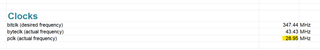
Pixel clock = 33 MHz


    • For our setup, we’ve determined that changing ili9881 related dsi parameters are needed to have discernable difference.
    • Once we’ve changed these two files and rebuilt the android image the touchscreen that it came with stopped working properly as expected; because the timings are different.
    • On the serialiser side, we’ve set the following registers:
      1. MODE SEL [1:0] – this is done via resistors (page 38 of serialiser datasheet)

The current setting is Splitter=0, DSI lanes=4, Clock=1 (FPD link is generated from DSI clock, DSI clock has to be in continuous mode), COAX=0 i.e. twisted pair cabling, DSI=0 i.e. enabled.


      1. Setup registers set for sync width config as described in page 17 of SNLA356 guide attached

                bufW[0]=0x40;                                                  //put port select in  indirect register 0x40

                bufW[1]=0x04;                                                  //set port 0

                bcm2835_i2c_write(bufW,2);

                bufW[0]=0x41;                                                  //put address in indirect register 0x41

                bufW[1]=0x30;                                                  //DSI_HSW_CFG_HI

                bcm2835_i2c_write(bufW,2);

                bufW[0]=0x42;                                                  //put data in indirect register 0x42

                bufW[1]=0x00;                                                  //DSI_HSW_CFG_HI=0

                bcm2835_i2c_write(bufW,2);

                bufW[0]=0x41;                                                  //put address in indirect register 0x41

                bufW[1]=0x31;                                                  //DSI_HSW_CFG_LO

                bcm2835_i2c_write(bufW,2);

                bufW[0]=0x42;                                                  //put data in indirect register 0x42

                bufW[1]=0x30;                                                  //DSI_HSW_CFG_LO=0x30 (48)

                bcm2835_i2c_write(bufW,2);

                bufW[0]=0x41;                                                  //put address in indirect register 0x41

                bufW[1]=0x32;                                                  //DSI_VSW_CFG_HI

                bcm2835_i2c_write(bufW,2);

                bufW[0]=0x42;                                                  //put data in indirect register 0x42

                bufW[1]=0x00;                                                  //DSI_VSW_CFG_HI=0

                bcm2835_i2c_write(bufW,2);

                bufW[0]=0x41;                                                  //put address in indirect register 0x41

                bufW[1]=0x33;                                                  //DSI_VSW_CFG_LO

                bcm2835_i2c_write(bufW,2);

                bufW[0]=0x42;                                                  //put data in indirect register 0x42

                bufW[1]=0x03;                                                  //DSI_VSW_CFG_LO=3

                bcm2835_i2c_write(bufW,2);


               bufW[0]=0x40;                                                  //put port select in  indirect register 0x40

               bufW[1]=0x04;                                                  //set port 0

               bcm2835_i2c_write(bufW,2);

               bufW[0]=0x41;                                                  //put address in indirect register 0x41

               bufW[1]=0x20;                                                  //DSI_CONFIG_0

               bcm2835_i2c_write(bufW,2);

               bufW[0]=0x42;                                                  //put data in indirect register 0x42

               bufW[1]=0x6F;                                                  //DSI_SYNC_PULSES=0

               bcm2835_i2c_write(bufW,2);


      1. Dsi lane config registers to match hardware connections.
    • I’ve attached the specs/datasheets accordingly. But unfortunately, the display is not working (we just see a black screen), perhaps you can help us toward the right direction.

Maybe there’s a guide/tutorial that you have that’s applicable to our setup?


Thank you for your time and efforts.

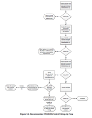
 MDT0430E5IHHC-RGB.pdfQuectel_SC668S_Series_Display_Driver_Development_Guide_V1.0.pdfsnla356 user guide.pdf

  • Hi Austin,

    Thanks for your question. I have a few follow up questions:

    • Does this ever happen with patgen (no DSI input), or only end-to-end (using DSI input)?
    • Is there lock between the 941AS and the 926 when this occurs?
    • When you make DSI configurations on the 941AS, please make sure you disable DSI in register 0x1. Once configurations are complete, then you can re-enable DSI.
    • The DSI bring-up guide you linked can be very helpful for debugging DSI issues. I would recommend following the Debug flow that is shown in this user guide:

    Regards,

    Ben

  • Hello Ben

    Thanks for the quick response sir!

    I hope with your help, our issue can be resolved!

    Please see the answers below:

    Does this ever happen with patgen (no DSI input), or only end-to-end (using DSI input)?

    We have the pattern generator working with no DSI input.

    Is there lock between the 941AS and the 926 when this occurs?

    Yes.

    When you make DSI configurations on the 941AS, please make sure you disable DSI in register 0x1. Once configurations are complete, then you can re-enable DSI.

    Yes we are now doing this.

    The DSI bring-up guide you linked can be very helpful for debugging DSI issues. I would recommend following the Debug flow that is shown in this user guide: Yes we will. Thank you.

    After further tests we have found that after running the pattern generator and then turning on the DSI signal we get an image from the DSI which is scrolling vertically. Do you know the reason for this?

  • Hi Austin,

    It is possible this is due to incorrect packet timing from the DSI source. Since the image is fine when using pattern generator, I believe this has to do with the DSI source. Please confirm the following with the DSI source:

    • LP-11 transitions should be implemented periodically
    • If in non-burst mode, the DSI rate should be related to the PCLK. Is the source in burst mode or non-burst mode? And what is the DSI rate?
    • Please check the packet structure with the DSI bring-up guide
    • Please make sure the timing sent by the DSI source is the correct timing

    Additionally, can you provide a reg dump of the 941AS?

    Regards,

    Ben

  • Hello Ben,

    Thanks for the response, apologies for the delayed response, we've been busy diagnosing our issue here in the lab.

    • LP-11 transitions should be implemented periodically

    We believe this is implemented, as the flags were set in the DSI source config (dtsi) files as shown in bold below (this is referenced in the bringup guide 4.1)

    &mdss_mdp {
    dsi_ili9881d_720p_video: qcom,mdss_dsi_ili9881d_720p_video {
    qcom,mdss-dsi-panel-name ="midas video mode dsi panel without DSC";
    qcom,mdss-dsi-panel-type = "dsi_video_mode";
    qcom,mdss-dsi-virtual-channel-id = <0>;
    qcom,mdss-dsi-stream = <0>;
    qcom,mdss-dsi-h-left-border = <0>;
    qcom,mdss-dsi-h-right-border = <0>;
    qcom,mdss-dsi-v-top-border = <0>;
    qcom,mdss-dsi-v-bottom-border = <0>;
    qcom,mdss-dsi-bpp = <24>;
    qcom,mdss-dsi-color-order = "rgb_swap_rgb";
    qcom,mdss-dsi-underflow-color = <0xff>;
    qcom,mdss-dsi-border-color = <0>;
    qcom,mdss-dsi-h-sync-pulse = <0>;
    qcom,mdss-dsi-traffic-mode = "non_burst_sync_event";
    qcom,mdss-dsi-lane-map = "lane_map_0123";
    qcom,mdss-dsi-bllp-eof-power-mode;
    qcom,mdss-dsi-bllp-power-mode;
    qcom,mdss-dsi-tx-eot-append;
    qcom,mdss-dsi-lane-0-state;
    qcom,mdss-dsi-lane-1-state;
    qcom,mdss-dsi-lane-2-state;
    qcom,mdss-dsi-lane-3-state;
    qcom,mdss-dsi-force-clock-lane-hs;
    qcom,mdss-dsi-dma-trigger = "trigger_sw";
    qcom,mdss-dsi-mdp-trigger = "none";
    qcom,mdss-dsi-lp11-init;
    qcom,mdss-dsi-bl-pmic-control-type = "bl_ctrl_wled";
    qcom,mdss-dsi-bl-min-level = <1>;
    qcom,mdss-dsi-bl-max-level = <4095>;
    qcom,mdss-dsi-reset-sequence = <1 10>, <0 10>, <1 10>;
    qcom,mdss-pan-physical-width-dimension = <74>;
    qcom,mdss-pan-physical-height-dimension = <131>;

    qcom,mdss-dsi-display-timings {
    timing@0{
    qcom,mdss-dsi-panel-width = <800>;
    qcom,mdss-dsi-panel-height = <480>;
    qcom,mdss-dsi-h-front-porch = <44>;
    qcom,mdss-dsi-h-back-porch = <38>;
    qcom,mdss-dsi-h-pulse-width = <50>;
    qcom,mdss-dsi-h-sync-skew = <0>;
    qcom,mdss-dsi-v-back-porch = <29>;
    qcom,mdss-dsi-v-front-porch = <8>;
    qcom,mdss-dsi-v-pulse-width = <3>;
    qcom,mdss-dsi-panel-framerate = <60>;
    qcom,mdss-dsi-on-command = [
    05 01 00 00 78 00 02 11 00
    05 01 00 00 05 00 02 29 00
    ];
    qcom,mdss-dsi-off-command = [05 01 00 00 14 00 02 28 00
    05 01 00 00 78 00 02 10 00];
    qcom,mdss-dsi-on-command-state = "dsi_lp_mode";
    qcom,mdss-dsi-off-command-state = "dsi_hs_mode";
    };
    };
    };
    };

    • If in non-burst mode, the DSI rate should be related to the PCLK. Is the source in burst mode or non-burst mode? And what is the DSI rate?

    as above; we're using non-burst sync event mode (however we tried all the other types and still no luck). We think the DSI clock rate reported from the register 0x5f is 29MHz (this was set in the other dtsi file required using qcom's spreadsheet macro) see in bold below:

    &dsi_ili9881d_720p_video {
    qcom,mdss-dsi-t-clk-post = <0x09>;
    qcom,mdss-dsi-t-clk-pre = <0x15>;
    // qcom,dsi-supported-dfps-list = <60 55 53 43>;
    // qcom,mdss-dsi-pan-enable-dynamic-fps;
    // qcom,mdss-dsi-pan-fps-update =
    // "dfps_immediate_porch_mode_vfp";
    // qcom,esd-check-enabled;
    // qcom,mdss-dsi-panel-status-check-mode = "reg_read";
    // qcom,mdss-dsi-panel-status-command = [06 01 00 01 00 00 01 0a];
    // qcom,mdss-dsi-panel-status-command-state = "dsi_hs_mode";
    // qcom,mdss-dsi-panel-status-value = <0x9d 0x9d 0x9d 0x9d>;
    // qcom,mdss-dsi-panel-on-check-value = <0x9d 0x9d 0x9d 0x9d>;
    // qcom,mdss-dsi-panel-status-read-length = <4>;
    qcom,mdss-dsi-display-timings {
    timing@0{
    qcom,mdss-dsi-panel-phy-timings =
    [1C 19 02 03 01 02 04 a0
    1C 19 02 03 01 02 04 a0
    1C 19 02 03 01 02 04 a0
    1C 19 02 03 01 02 04 a0
    1C 07 02 03 01 02 04 a0];

    qcom,display-topology = <1 0 1>;
    qcom,default-topology-index = <0>;
    };
    };
    };

    • Please check the packet structure with the DSI bring-up guide

    How do we do this?

    • Please make sure the timing sent by the DSI source is the correct timing

    We belive it is the correct timing as it's close to the timing stated in qcom's provided macro spreadsheet

    Additionally, can you provide a reg dump of the 941AS?

    please see the reg dump below:

    pi@raspberrypi:~ $ i2cdump -y 1 0x0c
    No size specified (using byte-data access)
    0 1 2 3 4 5 6 7 8 9 a b c d e f 0123456789abcdef
    00: XX 00 06 da 00 00 58 00 00 01 25 00 67 30 00 00 X.??..X..?%.g0..
    10: 00 00 00 8b 00 00 fe de 7f 7f 01 00 00 00 01 00 ...?..?????...?.
    20: 00 00 25 00 00 00 00 00 01 20 20 a0 00 00 a5 5a ..%.....? ?..?Z
    30: 00 09 00 05 0c 00 00 00 00 00 00 00 00 00 81 02 .?.??.........??
    40: 04 3b 03 00 00 00 00 00 00 00 00 00 00 00 00 8c ?;?............?
    50: 16 00 00 00 02 00 00 02 00 00 d9 00 07 06 44 1d ?...?..?..?.??D?
    60: 22 02 00 00 10 00 0d 1d 00 00 00 00 00 00 20 00 "?..?.??...... .
    70: 00 00 00 00 00 00 00 00 00 00 00 00 00 00 80 00 ..............?.
    80: 00 00 00 00 00 00 00 00 00 00 00 00 00 00 00 00 ................
    90: 00 00 00 00 00 00 00 00 00 00 00 00 00 00 00 00 ................
    a0: 00 00 00 00 00 00 00 00 00 00 00 00 00 00 00 00 ................
    b0: 00 00 00 00 00 00 00 00 00 00 00 00 00 00 00 00 ................
    c0: 00 00 82 00 38 00 21 00 40 00 00 00 00 02 ff 00 ..?.8.!.@....?..
    d0: 00 00 00 00 00 00 00 00 00 00 00 00 00 00 00 00 ................
    e0: 00 00 82 00 28 08 21 00 00 00 00 00 00 02 00 00 ..?.(?!......?..
    f0: 5f 55 42 39 34 31 00 00 00 00 00 00 00 00 00 00 _UB941..........

    then the indirect registers are:

    DPHY_TINIT_TIMING reg = 0x0
    DPHY_TERM_TIMING = 0x0
    DPHY_CLK_SETTLE = 0x1d
    DPHY_HS_SETTLE = 0x14
    DPHY_SKIP_TIMING = 0x3a
    DPHY_LP_POLARITY = 0x0
    DPHY_BYPASS = 0x0
    HSRX_TO_CNT = 0x0
    DPHY_STATUS = 0x77
    DPHY_DLANE0_ERR = 0x14
    DPHY_DLANE1_ERR = 0x10
    DPHY_DLANE2_ERR = 0x10
    DPHY_DLANE3_ERR = 0x0
    DPHY_ERR_CLK_LANE = 0x0
    DPHY_SYNC_STS = 0x7
    DSI_CONFIG0 = 0x6f
    DSI_CONFIG1 = 0x0
    DSI_ERR_CFG0 = 0xff
    DSI_ERR_CFG1 = 0x7f
    DSI_STATUS = 0x1
    DSI_ERRCNT = 0x8
    DSI_VC_DTYPE = 0x0
    DSI_ERR_RPT0 = 0x0
    DSI_ERR_RPT1 = 0x0
    DSI_ERR_RPT2 = 0x0
    DPHY_ERR_CLK_LANE = 0x0
    DSI_HSW_CFGLO = 0x24
    DSI_VSW_CFGHI = 0x0
    DSI_VSW_CFGLO = 0x1d
    DSI_SYNCDLY_CFGHI = 0x0
    DSI_SYNCDLY_CFGLO = 0x20
    DSI_EN_HSRX = 0x0
    DSI_EN_LPRX = 0x0
    DSI_EN_RXTERM = 0x0
    DSI_PCLK_DIVM = 0x2
    DSI_PCLK_DIVN = 0x3

    Apologies for any ignorance. This is my first time working on dsi-mipi. Any help from you is greatly appreciated!

    Thanks again for your time and efforts!

  • Hello Ben

    Just to add to my previous reply,

    I have just looked at the guide and I believe we do have lp11 transitions implemented as shown in the scope grab below:

    Thanks

  • Hi Austin,

    No worries at all, thanks for all the information. Are you using 4 DSI lanes? If you are, I believe the TSKIP count has been programmed incorrectly:

    PCLK = 29MHz

    fDSI = PCLK*12/4

    fDSI = 29MHz * 3 = 87MHz

    TSKIP_CNT = Round(65*.087GHz - 5) = 1

    So DSI Indirect Register 0x5 "DPHY_SKIP_TIMING" should be 0x5 = 0x2. Currently it is programmed to 0x3a.

    Please let me know if this solves your issue, if not, we will have to look closer at the DSI packets.

    Regards,

    Ben

  • Hello Ben

    Thanks for this! with your help there's an output from our display. However, the image ang borders aren't central but this can be adjusted later.

    Things I did:

    I also had to add a DIGITAL RESET1 (0x02) at boot up, before changing the dsi indirect/direct registers!

    As suggested, the DPHY_SKIP_TIMING had to be set to 0x02 (I had said this before, turns out its required) setting the DSI CLOCK from source wasn’t enough
    After this the DPHY_LANE_ERROR ( I was detecting mipi lane sync issues for lane 1 2 3) issue had gone; as verified by reading the indirect registers.
    You already know this but to fix the vertical scrolling issue I had to create a function to write on the indirect registers; the original functions only set the port 0 once, but it had to be set for every single register.

    now the i2c dump looks like:

    pi@raspberrypi:~ $ i2cdump -y 1 0x0c
    No size specified (using byte-data access)
    0 1 2 3 4 5 6 7 8 9 a b c d e f 0123456789abcdef
    00: XX 00 06 da 00 00 58 00 00 01 3d 3a 67 30 00 00 X.??..X..?=:g0..
    10: 00 00 00 8b 00 00 fe de 7f 7f 01 00 00 00 01 00 ...?..?????...?.
    20: 00 00 25 00 00 00 00 00 01 20 20 b8 00 00 a5 5a ..%.....? ?..?Z
    30: 00 09 00 05 0c 00 00 00 00 00 00 00 00 00 81 02 .?.??.........??
    40: 04 3b 03 00 00 00 00 00 00 00 00 00 00 00 00 8c ?;?............?
    50: 16 00 00 00 02 00 00 02 00 00 d9 00 07 06 44 1d ?...?..?..?.??D?
    60: 22 02 00 00 10 00 0d 1d 00 00 00 00 00 00 20 00 "?..?.??...... .
    70: 00 00 00 00 00 00 00 00 00 00 00 00 00 00 80 00 ..............?.
    80: 00 00 00 00 00 00 00 00 00 00 00 00 00 00 00 00 ................
    90: 00 00 00 00 00 00 00 00 00 00 00 00 00 00 00 00 ................
    a0: 00 00 00 00 00 00 00 00 00 00 00 00 00 00 00 00 ................
    b0: 00 00 00 00 00 00 00 00 00 00 00 00 00 00 00 00 ................
    c0: 00 00 82 00 38 00 21 44 40 00 00 00 00 02 ff 00 ..?.8.!D@....?..
    d0: 00 00 00 00 00 00 00 00 00 00 00 00 00 00 00 00 ................
    e0: 00 00 82 00 28 08 21 00 00 00 00 00 00 02 00 00 ..?.(?!......?..
    f0: 5f 55 42 39 34 31 00 00 00 00 00 00 00 00 00 00 _UB941..........

    and registers monitored:

    BCC status = 0x0
    Generat sts status = 0x7
    DSI pixel freq = 29
    DPHY_TINIT_TIMING reg = 0x0
    DPHY_TERM_TIMING = 0x0
    DPHY_CLK_SETTLE = 0x1d
    DPHY_HS_SETTLE = 0x14
    DPHY_SKIP_TIMING = 0x2
    DPHY_LP_POLARITY = 0x0
    DPHY_BYPASS = 0x0
    HSRX_TO_CNT = 0x0
    DPHY_STATUS = 0x1f
    DPHY_DLANE0_ERR = 0x0
    DPHY_DLANE1_ERR = 0x0
    DPHY_DLANE2_ERR = 0x0
    DPHY_DLANE3_ERR = 0x0
    DPHY_ERR_CLK_LANE = 0x0
    DPHY_SYNC_STS = 0x0
    DSI_CONFIG0 = 0x6f
    DSI_CONFIG1 = 0x0
    DSI_ERR_CFG0 = 0xff
    DSI_ERR_CFG1 = 0x7f
    DSI_STATUS = 0x0
    DSI_ERRCNT = 0x0
    DSI_VC_DTYPE = 0x3e
    DSI_ERR_RPT0 = 0x0
    DSI_ERR_RPT1 = 0x0
    DSI_ERR_RPT2 = 0x0
    DPHY_ERR_CLK_LANE = 0x0
    DSI_HSW_CFGLO = 0x24
    DSI_VSW_CFGHI = 0x0
    DSI_VSW_CFGLO = 0x1d
    DSI_SYNCDLY_CFGHI = 0x0
    DSI_SYNCDLY_CFGLO = 0x20
    DSI_EN_HSRX = 0x0
    DSI_EN_LPRX = 0x0
    DSI_EN_RXTERM = 0x0
    DSI_PCLK_DIVM = 0x2
    DSI_PCLK_DIVN = 0x3
    Interrupt status = 21
    Interrupt status = 21
    I2C set slave address 0x2c
    I2C set slave address 0x34
    I2C set slave address 0x0C

    Do you notice anymore registers that require modifying?

    Again, thank you very much for your time and efforts sir!

  • Hi Austin,

    Sorry for the delay, the E2E forums were undergoing maintenance at the end of last week. Since the DSI errors are gone, and the image can be displayed, it seems okay.

    Regards,

    Ben

  • Hello Ben

    Ok thanks for your help!

    Regards

  • Of course,

    Feel free to reach out with any more questions. I will close this thread for now.

    Regards,

    Ben