Other Parts Discussed in Thread: TCA9535, TCA9555
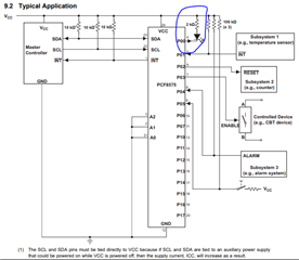
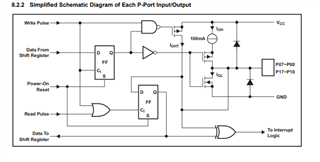
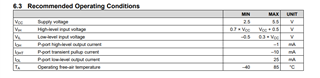
The data sheet seems to show that the IO expander is capable of supplying sufficient current ONLY during the write pulse. Otherwise, the current supplied from the expander is not enough (~100 uA). At first glance I thought that each output port provides around 25 mA.
I connected LEDs (15-20 mA Forward current, green and red with a 2V and 2.1V Vf) to the IOs and expected to get adequate brightness. That, however, didn't work.