This thread has been locked.

If you have a related question, please click the "Ask a related question" button in the top right corner. The newly created question will be automatically linked to this question.

DS90UB941AS-Q1: Debug with the Pattern Generator

Part Number: DS90UB941AS-Q1

Hi Team,

The customer uses an internal pattern generator to test if the hardware connection between master and slave is correct. Follow the "internal test pattern generation feature of the explore FPD-Link III IVI device", but it does not appear to have any graphic display on the screen. Could you please help check if the register configuration and flow are correct or complete: 

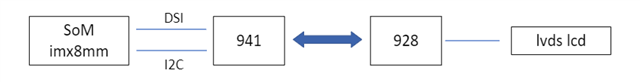
A simplified connection diagram is shown below and the LCD display is now debugged first: 

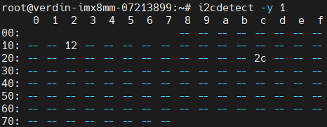
After starting the board, using i2c-tools, it can be seen that the 941 device address is 0x12:
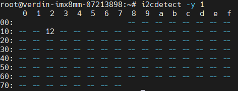
I2C_BUS_NUMBER=1

941_ADDR=0x12

Reading des_ID_des_ID_1 register 0x06 has a value of 0x76, and shifting right by one bit results in a 928 deserializer ID of 0x3B:

Then execute the script for the register configuration of the pattern generator, “941as_800x480p_PATGEN.sh”, using the internal timing and the internal pclk:

#!/bin/bash

# 800x480p60, Dual Link FPD III
# PCLK = 33.264MHz
# DSI clock = 99.792MHz
# DSI Lane Speed = 199.584Mbps/lane
# 4 Lanes DSI
# DSI input port 0
# Pattern Generator Mode
# Internal clock and Internal
# use i2c-tools to debug

set -e

I2C_BUS_NUMBER=1
UB941AS_ADDR=0x12

# Reset
i2cset -y -f -r $I2C_BUS_NUMBER $UB941AS_ADDR 0x01 0x02

# sleep 0.1s
sleep .1

# Disable DSI
i2cset -y -f -r $I2C_BUS_NUMBER $UB941AS_ADDR 0x01 0x08

# Select FPD-Link III Port 0 (default port0)
i2cset -y -f -r $I2C_BUS_NUMBER $UB941AS_ADDR 0x1E 0x01

# 1. Set Pixel Clock and Active Frame Size
# pixe clock = 33.264MHz divider = 200/33.264 ≈ 6
# hactive = 800 vactive = 480
#
i2cset -y -f -r $I2C_BUS_NUMBER $UB941AS_ADDR 0x66 0x03
i2cset -y -f -r $I2C_BUS_NUMBER $UB941AS_ADDR 0x67 0x06

i2cset -y -f -r $I2C_BUS_NUMBER $UB941AS_ADDR 0x66 0x07
i2cset -y -f -r $I2C_BUS_NUMBER $UB941AS_ADDR 0x67 0x20

i2cset -y -f -r $I2C_BUS_NUMBER $UB941AS_ADDR 0x66 0x08
i2cset -y -f -r $I2C_BUS_NUMBER $UB941AS_ADDR 0x67 0x03

i2cset -y -f -r $I2C_BUS_NUMBER $UB941AS_ADDR 0x66 0x09
i2cset -y -f -r $I2C_BUS_NUMBER $UB941AS_ADDR 0x67 0x1E

# 2. Set Total Frame Size
# Total H Width = 40(hback porch) + 800(hactive) + 40(hfront porch) + 48(hsync len)
# = 928 = 0011 1010 0000
# Total V Width = 31(vback porch) + 480(vactive) + 13(vfront porch) + 1(vsync len)
# = 525 = 0010 0000 1101
#
i2cset -y -f -r $I2C_BUS_NUMBER $UB941AS_ADDR 0x66 0x04
i2cset -y -f -r $I2C_BUS_NUMBER $UB941AS_ADDR 0x67 0xA0

i2cset -y -f -r $I2C_BUS_NUMBER $UB941AS_ADDR 0x66 0x05
i2cset -y -f -r $I2C_BUS_NUMBER $UB941AS_ADDR 0x67 0xD3

i2cset -y -f -r $I2C_BUS_NUMBER $UB941AS_ADDR 0x66 0x06
i2cset -y -f -r $I2C_BUS_NUMBER $UB941AS_ADDR 0x67 0x20

# 3. Set Back Porch
# H Back Porch = 40 = 0010 1000
# V Back Porch = 31 = 0001 1111

i2cset -y -f -r $I2C_BUS_NUMBER $UB941AS_ADDR 0x66 0x0C
i2cset -y -f -r $I2C_BUS_NUMBER $UB941AS_ADDR 0x67 0x28

i2cset -y -f -r $I2C_BUS_NUMBER $UB941AS_ADDR 0x66 0x0D
i2cset -y -f -r $I2C_BUS_NUMBER $UB941AS_ADDR 0x67 0x1F

# 4. Set Sync Widths
# H Sync Width = 48 = 0011 0000
# V Sync Width = 1 = 0000 0001
i2cset -y -f -r $I2C_BUS_NUMBER $UB941AS_ADDR 0x66 0x0A
i2cset -y -f -r $I2C_BUS_NUMBER $UB941AS_ADDR 0x67 0x30

i2cset -y -f -r $I2C_BUS_NUMBER $UB941AS_ADDR 0x66 0x0B
i2cset -y -f -r $I2C_BUS_NUMBER $UB941AS_ADDR 0x67 0x01

# 5. Set Sync Polarities
i2cset -y -f -r $I2C_BUS_NUMBER $UB941AS_ADDR 0x66 0x0E
i2cset -y -f -r $I2C_BUS_NUMBER $UB941AS_ADDR 0x67 0x00

# 6. Enable Pattern Generation
i2cset -y -f -r $I2C_BUS_NUMBER $UB941AS_ADDR 0x65 0x03
i2cset -y -f -r $I2C_BUS_NUMBER $UB941AS_ADDR 0x64 0x11

Could you please help check this case? Thanks.

Best Regards,

Cherry

  • Hello Cherry,

    due to the delay caused by the E2E maintenance, we will get back to you on Monday!

  • Hi Cherry,

    i2cset -y -f -r $I2C_BUS_NUMBER $UB941AS_ADDR 0x65 0x03
    i2cset -y -f -r $I2C_BUS_NUMBER $UB941AS_ADDR 0x64 0x11

    The following commands set the patgen to display a black pattern first. It also sets the timing select to take the timing from external video. Can you set 0x65[2]=1? This will enable the pattern generator to create it's own video from the timing which you have programmed.

    Regards,

    Ben

  • Hi Ben,

    Thank you for the support.

    When the 941 enables the pattern generator, is there a way to feedback if the 928 is generating the test video correctly? Such as by reading certain register values. 

    Thanks and regards,

    Cherry

  • Hi Cherry,

    There is not a way to check the timing from the 928. Is the patgen still not working?

    Regards,

    Ben

  • Hi Ben,

    Can you set 0x65[2]=1? This will enable the pattern generator to create it's own video from the timing which you have programmed.

    Setting 0x65[2]=1 and set the graphic to "red/cyan" for easy viewing, but there is still no test graphic on the screen.

    Also,

    1) Reading the DES_ID_DES_ID_1 register 0x06 can read the id of the deserializer, does this indicate that the connection between master and slave devices is OK?

    2) What settings are needed if they want to access touch ic etc. hanging from behind the device via i2c? For example, touch ic address is 0x41, as the manual mentioned to set i2c mode, and also set slave id, etc, could you help give an example?

    3) The master device is automatically recognized after the slave device is connected properly, if direct access to the slave device via i2c is required, is access to the touch hanging behind the slave device in question 2 the same method of operation? 

    Thanks and regards,

    Cherry

  • Hi Cherry,

    1) Reading the DES_ID_DES_ID_1 register 0x06 can read the id of the deserializer, does this indicate that the connection between master and slave devices is OK?

    This register would indicate that there was link at some point. It would be better to look at bit 0 of register 0xC of the 941AS for link detect, or Register 0x1C of the 928 to determine if there is lock.

    2) What settings are needed if they want to access touch ic etc. hanging from behind the device via i2c? For example, touch ic address is 0x41, as the manual mentioned to set i2c mode, and also set slave id, etc, could you help give an example?

    If the communication to the touch device is I2C, then the customer will likely want to set up an alias, which can be set up on the 941AS using the SlaveID and SlaveAlias registers. I2C passthrough will also need to be enabled by register.

    Regards,

    Ben

  • Hi Ben,

    Thank you for the response.

    941 address: 0x12

    After power-up, no other configuration is made, only register 0x3 is configured with a value of 0x28 to turn on I2C direct mode so that the registers from the slave device can be accessed. When I2C is set to pass-through, from i2cdetect it  can be seen the address from slave 928 as 0x2c:

    Then checking register 0xC for 941AS and register 0x1C for 928, 941 register 0xC value is 0x03 and 928 register 0x1C value is 0x03.

    And as you can see, the 941 register 0xC bit0 = 1, bit1 = 1. According to the manual, this indicates that a cable link was detected but a CRC error occurred during communication with the deserializer. What might be the problem with this error after power-up without additional operation and configuration? Is bit1=1 possibly causing the above screen no display issue? 

    Thanks and regards,

    Cherry

  • Hi Cherry,

    I am glad the 928 now has lock and the I2C address can be recognized. The CRC error may have to do with hardware, or it could be a CRC leftover from startup. Is the customer using a custom PCB or EVMs?

    Also, can you check the mapsel on the 928 and make sure the display can receive the selected color mapping?

    There are also tables in the 928 datasheet which show the different color schemes.

    Regards,

    Ben

  • Hi Ben,

    can you check the mapsel on the 928 and make sure the display can receive the selected color mapping?

    After setting the mapsel, it worked!

    Customer uses 941 with 928, and the graph generator's manual mentions that if 928 is used, 0x39 needs to be configured to start the graphics generator internal clock. The pattern is visible with or without register configuration. So the pattern generator internal clock here refers to which internal clock?

    That is, the 941 can generate the internal clock to the 928 and back to the LCD, or the 928 can generate its own internal clock directly to the LCD? Is it correct ?

    Thanks and regards,

    Cherry 

  • Hello Cherry,

    If you are using internal CLK pattern generator, this will use the internal Oscillator from the same device. So, if you are generating the pattern on the 928 it will use it's own internal clk.