This thread has been locked.

If you have a related question, please click the "Ask a related question" button in the top right corner. The newly created question will be automatically linked to this question.

DP83640T-EVK: How to program DP83640 for tiime synchronization on a custom PCB

Part Number: DP83640T-EVK
Other Parts Discussed in Thread: DP83640, USB-2-MDIO

Hello,

I am a student in Karlsruhe Germany and using the DP83640 Evaluation board for time synchronization for our Research project and I do not understand how to program it.

The thing is I am used to use SPI I2C communication protocols for accessing registers of a sensor or an IC but this IC says that it needs MDIO interface for communication and I am unable to find any help on internet what is MDIO interface. In your software section there are 4 downloadable and one of them is USB-2-MDIO GUI based software and it does not work on windows 11 I guess, and it also says that if only works on Windows XP. So, I wanted to know if there some software that I am missing or how do you program this device.

I am using STM32H723ZG microcontroller.

As a student I am not professional is these things but as far as I know there must by a clock and data lines for data communication. and a microcontroller which actually communicates with the device. So, I must have ana IDE for writing the code for which I am using STM32 CubeIDE and Cube MX for initializing the clocks, GPIOs etc. Now the problem is there 2 3 ways to communicate this device DP83640 and I need to program it using the JTAG. My question is that is there some IDE that TI provides or can the Cube IDE be used to programming this device as this device does not have a built-in controller or processor. Is it a preprogrammed device which has the working software in it already and I just need to Initialize it using MDIO. What is this MDIO? and like STM HAL Libraries are there any libraries from your side?

There are several connections to this device. The JTAG has pins named TDI, TRST, TMS, TDO, TCK but the data sheet says it is programed via the MDIO interface for accessing registers and for MAC and PHY connectivity MII or RMII is needed so How do I do it. 

The idea is that there are 2 boards (1 NVIDIA Jetson TX2 and a custom sensor PCB) and this DP83640 is on the sensor board.  A master clock will come to this device from TX2 platform via ethernet and then I need to synchronize the time of a local clock on this sensor board so that the working of TX2 and sensor board can be on the same time with time stamps.

  • Addition:

    I got to know that the JTAG is only for Boundry Scan purpose only so it can not be used for configuration. And I have figured out a way to configure this device via HAL the MDIO interface provided by STM32 HAL libraries for ethernet communication. So other than this part please guide me for the rest.

  • Hi Muhammad!

    I understand your frustration and I hope that I can help you.

    MDIO is a Serial Management Interface (SMI) defined by IEEE 802.3 Clause 45. In short, it's a way to manage the PHY via two pins: MDC & MDIO. MDC is the clock and MDIO is the actual data being sent.

    USB-2-MDIO definitely works with Windows 10, as that is what I currently use, but I am unaware if Windows 11 supports it. Are you unable to download it? What happens when you try to open the GUI?

    Have you gone through the DP83640T Demo Board User Guide? Section 2.3 Device Register Access gives a few options for accessing them. I'm afraid that this is an old board and support is limited to this User's Guide. I'm not sure if we have this board in my office, but tomorrow I will search and see if I can read/write registers to it. Until then please double check the User's Guide linked above.

    Regards,

    Alvaro

  • Hi Alvaro,

    1) I understood the MDIO interface I was just curious that if TI provides this interface in C/C++ libraries (API). Anyways I am able to configure the device using the HAL ethernet API for now.

    2) And yes I have tried the USB-2-MDIO software already, I am able to download it, open GUI as well but the problem is that the board is not being recognized by the windows as shown in the picture.

    So I cannot use this software for accessing the registers.

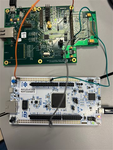
    The picture below is the setup for accessing the registers using STM32 Nucleo board and HAL libraries.

    3) Now here comes the real issue: This evaluation board is just for testing, The real board (a custom PCB) I need to program does not have these separate pins for MDIO interface and also the USB-2-MDIO software does not work. So I am looking for some other way for programming that board. May be I have to solder these pins temporarily just for the configuration but that is not going to be an efficient solution. So if there is some other way please let me know.

  • Hi Muhammad,

    The only way to program the PHY is through the MDC & MDIO pins. There is no other way

    Regards,

    Alvaro