This thread has been locked.

If you have a related question, please click the "Ask a related question" button in the top right corner. The newly created question will be automatically linked to this question.

TCAN4550-Q1: TCAN4450

Part Number: TCAN4550-Q1

Hi TI team,

we are using CC2340R as a MCU and TCAN4450 (TI) IC for CAN communication. In CAN datasheet, a clock-out pin shows for CAN clock. 

1. We are using external 48Mhz crystal for radio communication and 48Mhz internal crystal is also there in CC2340 MCU. How can we use internal 48Mhz crystal oscillator of MCU for CAN clock by clk-out pin (as shown in datasheet)?

2. Can we make any GPIO as clock-out (20Mhz/40Mhz) in MCU ?

3. What are the other possibilities ? 

4. We use buck converter in our design (Input - battery and output 3.3V). In that case we are are not enabling voltage regulator by INH pin (CAN IC) and left open, is that ok.

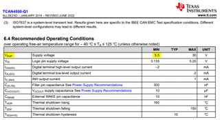
5. We are giving 3.3V to Vsup, WAKE, Vin. 

Thanks

Munesh Tripathi

  • Hello Munesh,

    1 & 2. This is the "Interface forum" that supports the TCAN4550-Q1.  If you are asking how to configure the CC2340R, you will need to create a post for the CC2340R part number instead of the TCAN4550-Q1 because my expertise in this forum is with the TCAN4550-Q1. 

    However, with that said, the 48Mhz is not a common frequency that is recommended for CAN applications and may or may not allow the CAN timing configuration for your desired nominal and data bit rates.  Also, there are a number of clock tolerance equations in the CAN standard that need to be satisfied in order to ensure stable CAN communication.  Many times, clocks derived from MCU's don't have the required tolerance for higher data rates, so this would also be something that needs to be evaluated with a MCU output clock.

    What are your nominal and data timing requirements and what does your CAN bus look like, length, number of nodes, is it linear or contain lots of stubs, etc.?

    3. The TCAN4550-Q1 usually is used with either a quartz crystal, or a crystal oscillator operating at either 20MHz or 40MHz. 

    The quartz crystal will be used with the TCAN4550-Q1's Pierce Oscillator Transimpedance Amplifier that sources current out the OSC1 pin and the OSC2 monitors the input clock. 

    The crystal oscillator will usually create a single-ended clock that swings between GND and VIO where the OSC1 pin becomes the clock input and OSC2 pin should be connected to GND.

    See more information in the TCAN455x Clock Optimization and Design Guidelines application note.

    4. If INH is not used, it is ok to leave it open.

    5. The TCAN4550-Q1 has a minimum operating supply voltage on VSUP of 5.5V this is because there is an internal 5V LDO that is used for CAN.  If VSUP drops below 5V, the device will enter a Under voltage protected mode.


    You will not be able to operate the device with VSUP = 3.3V.  You can use 3.3V for VIO which sets the digital IO signal levels for proper communication with the MCU.

    Regards,

    Jonathan