This thread has been locked.

If you have a related question, please click the "Ask a related question" button in the top right corner. The newly created question will be automatically linked to this question.

TCAN1044AV-Q1: CAN transceiver chip TCAN1044 and CAN communication problems

Part Number: TCAN1044AV-Q1

Hi,all

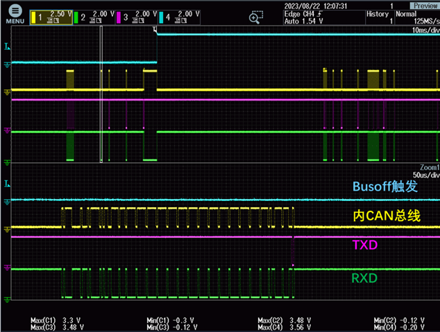
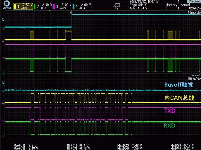
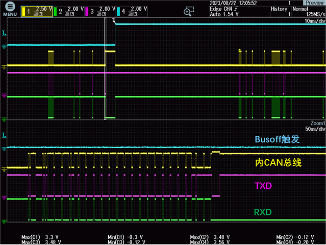
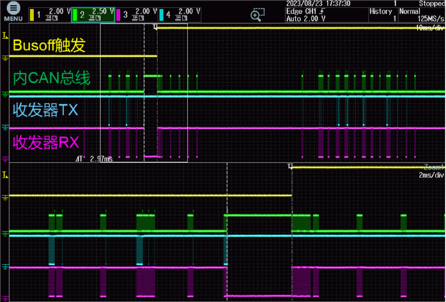
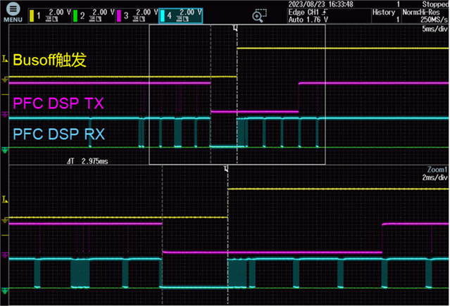
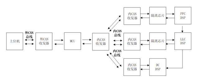
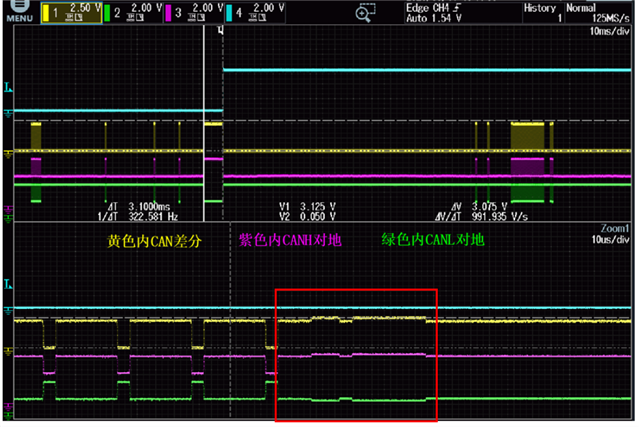
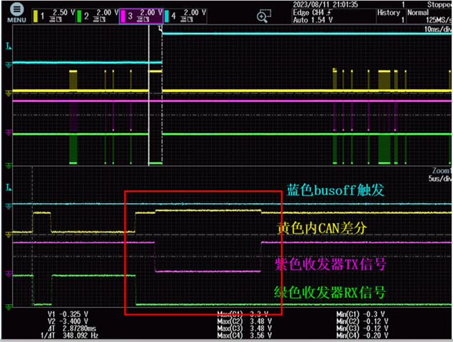
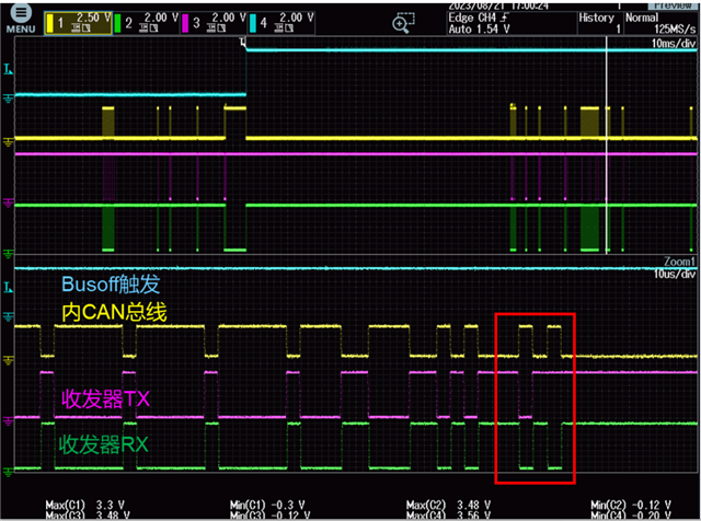
Problem background: The communication structure is shown in Figure 1. When the upper computer sends instructions, the CAN bus will trigger bus busoff for some reasons, resulting in the bus failing to receive subsequent instruction delivery. After finding out the reason, it is found that the communication signals on the CAN bus and between the MCU and the CAN transceiver are interfered, as shown in Figure 2 and Figure 3, and Figure 4 is the signal normally transmitted by the bus. The blue waveform in Figure 3 is the GPIO state of MCU, and the logic is that the level is flipped once when busoff is encountered, which is used to capture other signals in the moment triggered by busoff. The CAN bus state is consistent with the RX level, indicating that the CAN bus is in the state of transmitting DSP data back to the MCU at this time, because the abnormal RX signal causes the MCU to recognize the BUSOFF and close the bus.

Requirement 1: In the red box as shown in Figure 2, does TCAN1044 have any mechanism that will affect the CAN bus level?

Requirement 2: As shown in the red box in Figure 3, CAN bus is in the state of returning data, and the level is slightly elevated. How is this abnormally elevated part affected? Will it be caused by the low level signal of TX?

Requirement 3: As shown in Figure 3, when the MCU is sending data and receiving the return data at the same time, the bus is in the return state. At this time, can the bus receive the data sent by the MCU to the bus?

Picture 1:
Picture 2:
Picture 3:
Picture 4:
  • Hi Zhixia,

    Thanks for sharing your question on E2E and including detailed waveforms of your findings. 

    Picture 2 and 3 appear to show the local node reacting to an error it perceives on the CAN bus. The node indicates that it has seen an error by driving 6 consecutive dominant bits on the bus. We can see the TXD signal go low for the correct amount of time for this. This also lines up with the elevated differential voltage on the bus because multiple transceivers are driving the dominant signal at the same time. I do not see any issues with the CAN frame before this point, so it is difficult to say why the node has driven the error frame. Has the node reported a specific error? Something like CRC Error, BIT1 Error, etc. If you share a scope shot showing the whole CAN frame where the bits are visible, we may be able to tell in which part of the frame the error is being recognized.

    There is something else odd about this capture: after the error frame, we would normally expect the bus the return to an idle recessive state. However, in this case we see the bus remain in the dominant state for ~3ms. This is consistent with the time for a dominant state timeout for a CAN transceiver, so I suspect that the transmitting node has its TXD signal stuck low. This is not common for a CAN system so the failsafe feature of the transceiver stops the node from overriding the bus during this fault. Do you know why the transmitting node may be holding the TXD signal low?

    The analog waveforms here look good and it appears that the transceiver is operating well. This is most likely an issue with the CAN controllers operating in the system. This could be a configuration issue, a timing problem, an IO problem, or something else similar. 

    Let me know if any of this is unclear and if you have any ideas why the CAN controllers may be acting this way.

    Regards, 
    Eric Schott 

  • Hi,Eric

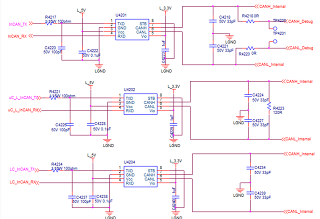
    1、The following is to supplement the complete CAN frame waveform data and schematic part:

    Picture 1:MCU to CAN bus schematic section

    Picture 2:Schematic sections of the other three transceivers

    Picture 3:CAN communication normal transmission waveform

    Picture 4:CAN Abnormal node waveform

    2、Question 1:Please help to find the direction of some problems according to the complete CAN frame triggered by the fault, or to determine which frame action is wrong, thank you.

    Question 2:The CAN data in Figure 4 corresponds to the RXD data, and the bus status is to transmit data back to the MCU. Can it be understood in this way?

    Question 3: If question 2 is correctly understood, when CAN bus sends back data, will TXD send data conflict with the data state sent back by the bus? If the description of question 2 is wrong, please help to describe the current CAN bus sending and receiving status, thank you.

    Question 4:The abnormal bus is caused by the abnormal low level of TXD, can you understand it this way?

  • Hi Zhixia,

    Thanks for the extra information with schematic and additional waveforms. At this point I am still unsure what could be causing this issue, as the node we are observing in picture 4 seems to be operating as expected. I believe it may be some other node that is misbehaving and causing this odd bus state. 

    Question 1:Please help to find the direction of some problems according to the complete CAN frame triggered by the fault, or to determine which frame action is wrong, thank you.

    In Picture 4 we see the local node transmitting data to the bus. The CAN bus and RXD signal match what is being transmitted on the TXD signal the whole frame up until what appears to be the ACK phase of the CAN frame. At this point we see the TXD signal go idle while the CAN bus and RXD signal go dominant for one bit time. This is other node(s) acknowledging that they have received the transmision without any errors. All of this is normal and expected for propper CAN communication. 

    The odd part is what happens next: the local node drives to bus dominant again very soon after the ACK (last TXD low pulse) and other nodes immediately redrive the error frame (elevated VOD on the CAN bus). This would be expected system behavior if the local node tried to transmit without waiting for the correct amount of intermission time in between CAN frames. Again, this would be an expected response if the local node was misbehaving. 

    After this though is a very unexpected behavior: the CAN bus remains dominant for far too long. The idle state for CAN is always recessive (logic 1) as this is the state that can be overridden by any device that needs to drive a dominant (logic 0) to initiate communication. No controller should ever hold the bus dominant for this long and the problem node eventually has its transceiver's failsafe dominant timeout function activate and disables itself, allowing the bus to return to a recessive state. 

    I recommend finding out which node is holding the bus dominant for this long period and disconnecting it from the bus. I'm curious if this will resolve both issues, or only the bus stuck state. In order to find the node, probe the TXD signals and look for the one that remains low for > 2ms.

    Question 2:The CAN data in Figure 4 corresponds to the RXD data, and the bus status is to transmit data back to the MCU.

    I'm not sure which direction is the reference here when you say "back to the MCU". Do you have a block diagram that you can share for my reference of the data path in this setup?

    Regards,

    Eric Schott 

  • Hi,Eric

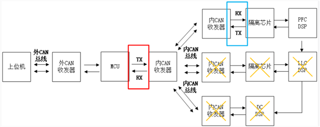
    The communication architecture and waveform are provided below. The red box marks in Figure 1 correspond to TX/RX in Figure 2, and the blue box marks correspond to TX/RX in Figure 3. The communication path is from the host computer to the MCU to the PFC DSP(LLC DSP and DC DSP do not work), both of which are two-way communication.

    Figure 1:

    Figure 2:

    Figure 3:

    Figure 4:

    Question 1: According to the analysis in Figure 3, PFC DSP TX signal has an abnormally low level of 10ms. Will this level cause the bus to be in a dominant state and cause busoff failure? CAN the CAN bus be considered abnormal because of abnormal data node sent by DSP?

    Question 2: Why does RX in Figure 3 have a low level of 2.975ms? Is this state caused by abnormal low level of TX data sent by DSP?

    Question 3: PFC DSP TX has a low level of 10ms, and TXD explicit timeout protection is triggered when TX enters the TCAN1044 chip, and CAN signal abnormal time reaches 2.975ms and is reset,therefore, the RX waveform of MCU in Figure 2 is only 2.975ms. Can we understand it in this way?

    Best Regards,

    Zhixia Bai

  • Hi Zhixia,

    Question 1: According to the analysis in Figure 3, PFC DSP TX signal has an abnormally low level of 10ms. Will this level cause the bus to be in a dominant state and cause busoff failure? CAN the CAN bus be considered abnormal because of abnormal data node sent by DSP?

    Yes, a dominant state of this length is an issue and can cause the bus to go into a bus-off state. 

    Question 2: Why does RX in Figure 3 have a low level of 2.975ms? Is this state caused by abnormal low level of TX data sent by DSP?

    Question 3: PFC DSP TX has a low level of 10ms, and TXD explicit timeout protection is triggered when TX enters the TCAN1044 chip, and CAN signal abnormal time reaches 2.975ms and is reset,therefore, the RX waveform of MCU in Figure 2 is only 2.975ms. Can we understand it in this way?

    The 10ms dominant on TXD from the DSP is abnormal and should be analyzed so that this behavior can be resolved. The ~3ms timeout is a feature of the TCAN1044A to disable the driver if TXD is stuck low to allow the bus to recover. This is expected behavior from the transceiver.

    Regards, 
    Eric Schott