This thread has been locked.

If you have a related question, please click the "Ask a related question" button in the top right corner. The newly created question will be automatically linked to this question.

SN65HVD1781-Q1: RS485 reserved and unpopulated pull-up resistors

Part Number: SN65HVD1781-Q1

Hi,

After a conversation with Jonard at Customer Support sends the task on here.

 I looked at that drawing, but I don't understand if those resistors should be included or not.

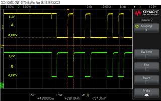
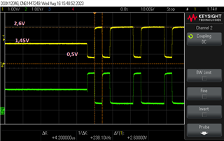
Added pictures of both signals, A and B with / without pull-up resistor.

I don't know what voltage level those pulses should be with. There is talk of high and low level, but in our case it should be 3.2V and 0V, which is not shown, either with or without pull-up resistor.

Without this resistor, the voltage level appears to reach half of the total voltage when no messages are sent.

The scope shows that the signal is reduced without these resistors.

All this gives rise to several questions.

The first question is whether it is correct with both pull-ups. Will one pull-up to a high level and the other to a low level?

In which of these, A or B should have a high level, or both?

The resistors are 1K, what is the effect on the signal if we increase the resistor?

I see that there is an error with the resistors on my schematic, a double has been added. So we removed a couple.

should the resistors be at the input to the chip or can they be connected after the series resistors?

Finally, we have removed all the resistor and the system works flawlessly with or without the them.

We use RS485 which is split into µC and the display with a short length of approx. 150 mm, where the communication is connected to another three µC.

I'm new to this with RS485 and really need help with this, hoping we get a slightly more thorough explanation about these counter starters that are labeled these are "reserved and unpopulated".

Hope you understand my concerns.

Regards

Jose
  • Hi Jose,

    First I have a question - is there another RS-485 device between RS-485 bus and UC1? In general the RS-485 bus shouldn't be directly attached to a microcontroller (those are the A/B pins) since RS-485 standard allows -7V to 12V on the bus that could damage most microcontrollers. 

    For your direct questions:

    1. Usually when bias resistors (also called fail-safe resistors) are added to the bus a resistor will go between device VCC and A and another resistor will go between device GND and B. If these are added - then only 1 pair is added for the entire bus. You do not need these to operate any RS-485 bus - but they are common. The reasons to use them are two-fold.

    1a) The first reason you'd see them is to give a common bias - this is so the bus is centered usually at VCC/2. In these use cases the pull-up on A and pull-down on B are going to be weak as to not overload the bus and if the system is terminated the voltage across termination will be ~0V. 

    1b) The second reason you'd see them is to create an idle fail-safe. Classical RS-485 has a undefined logic state at a differential input of 0V - which means the output can glitch when the bus is idling. To prevent this you can create a differential bias during idle with a pull-up on A and a pull-down on B which sets the bus to 200mV or slightly above to guarantee that during idling you will have a constant high output from the "R" pin. In modern devices the fail-safe feature is integrated by making 0V a logic high so in cases of idling and also open and short bus conditions the output at "R" will remain high -you still may see fail-safe resistors - but they are there to increase noise margin on fail-safe devices instead providing a fail-safe. These resistors will be stronger - the sizing really depends on on how many nodes are on the bus and the unit loading of the transceiver. We have a good application note of these resistors, how to size them, and impact to bus: https://www.ti.com/lit/an/slyt324/slyt324.pdf. Please note that you only add 1 pair of bias resistors per bus because RS-485 devices cannot driver a common mode loading of less than 375 Ohms. 

    2 and 3. It doesn't seem your bus has termination resistors (in RS-485 both terminal nodes should have a 120 Ohm termination between A and B (that 120 value can change due to the fail-safe resistors as the load should equal 120 Ohms when altogether). If you don't add terminations (in shorter buses you may not need to) the bias resistors are going to bias the bus close to VCC on A and GND on B - it really doesn't matter if you put it outside the series resistor or not because each node is only drawing uA of current. Terminations make the math messier - but give a cleaner signal so you can still set your pair of bias resistors wherever - but you just need to account for it at each node - it would be simplest to have series resistors in series with input pins and then have terminations and fail-safes on the outside as that will clean up the math and make it an easier problem to solve. So if you have terminations and there is 2 to 3 nodes on the line you will have a differential bias of about >100mV and <200mV - this could be slightly skewed by series resistors. 

    Please let me know on connection to uC1!

    Best,

    Parker Dodson