This thread has been locked.

If you have a related question, please click the "Ask a related question" button in the top right corner. The newly created question will be automatically linked to this question.

SN65DPHY440SS: Application problem.

Expert 2050 points
Part Number: SN65DPHY440SS


Hi,

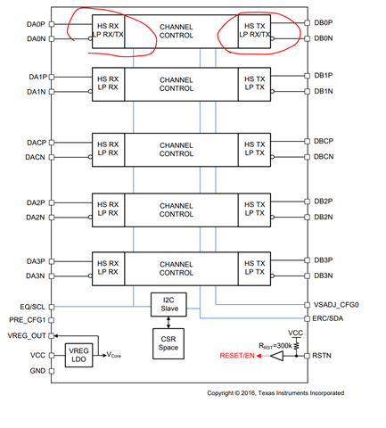
camera sensor --->retime-->SOC

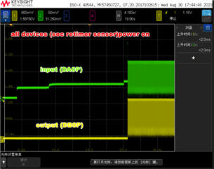
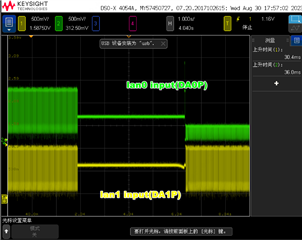
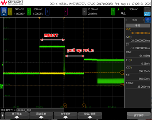
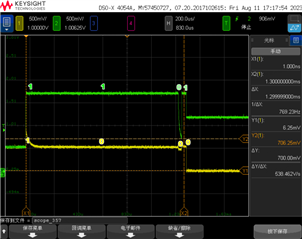
1. The camera SENSOR and retime are powered on simultaneously, and the waveform is normal. The waveform is as follows.

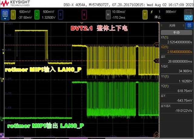
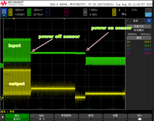
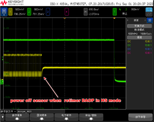
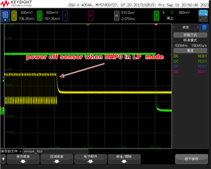
2.If only the camera module sensor is powered off and the retimer remains powered on, and then the sensor is powered on again, there is no output issue with the retimer mipi's lane0. The input waveform of lane0 is as follows (the second picture shows the details of the first step of powering on)

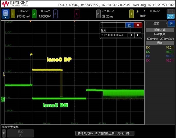
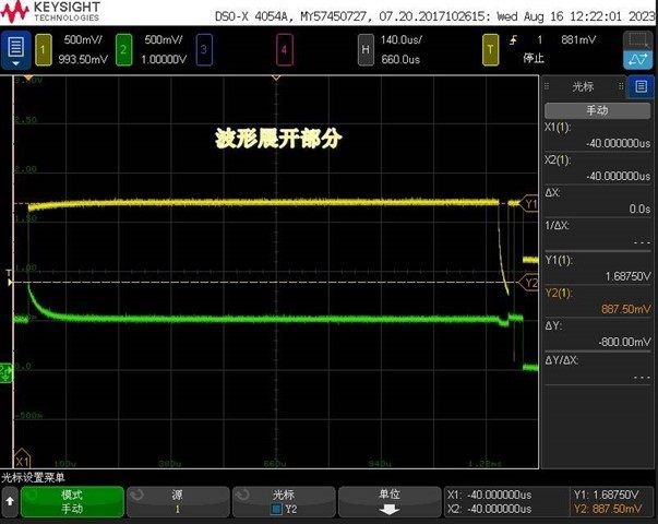
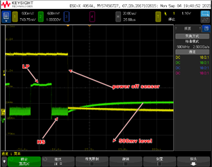
3. There is no such issue with the retimer's Lane1. Lane0 may generate some abnormal waveforms due to the module being powered on.

Have these abnormal waveforms affected the retimer's working state?

  • Hi,

    The DPHY440 lane 0 is a special lane. It supports DSI LP Backchannel. So, theDPHY440’s LP TX will expect to connect to an unterminated LP RX. With Lane 0 path (DA0P/N and DB0P/N) supporting bi-directional LP signaling, it is very important that DB0P/N LP TX is connected to an unterminated LP RX. If DB0P/N LP TX is connected to an HS RX, then LP signaling will not be able to reach the LP11 levels and which will cause the DPHY440 to not enable HS data path on Lane0.

    Thanks

    David

  • Hi~The following questions to help feedback

    1. Our current application is CSI. Your reply is that the TX end of retimer on DSI application should be connected to RX with no definite terminal connection. Our problem phenomenon is that the RX end of retimer is connected to the terminated TX, which has an impact on retimer

    2. Since the RX of Retimer is connected to the TX that may have uncertain terminations, we measure the sequence waveform of the receiving RX end of retimer (DA0P/N) as shown in the following figure (11 - >10 - >00 - >11), which will cause retimer to fail to work normally. What mode will this waveform sequence cause retimer to enter? Does the retimer enter an abnormal working mode and cannot enter the HS mode properly?

  • Hi,

    In order to support DSI, DPHY440 lane 0 is different from all the other lanes as shown below.

    So you can see lane 0 has LP TX and RX at both input and output. Since it has both LP TX and RX, the DPHY440 lane 0 output expect to see an unterminated TX. 

    When the sensor is powering on again, I think the DPHY440 is not seeing the unterminated TX and therefore will not go from LP to HS mode. This is why you are not seeing an output on lane 0.

    Thanks

    David

  • Thank you for your reply

    1. I can confirm that only lan0 has this problem at present

    2. DPHY440 lan0 is designed to support DSI. Does CSI also have this problem?

    3, why is the output expect to see unterminated TX, this sentence I do not understand, should not be input DA0P/N expect to see unterminated RX?

    4. When the camera is powered on again, it will send (11-10-00-11) waveform sequence to DPHY440 input DA0P/N, because this is an unterminated  RX, so it will not enter HS from LP.

    5. What state does the above waveform sequence put DPHY440 into?

  • Hi,

    DPHY440 supports both DSI and CSI. In order to support DSI, lane 0 has to support LP backchannel which means lane 0 is the only lane that needs to support bi-directional LP signaling. The CSI does not have such requirement. But if you are using lane 0, you have to keep in mind the fact that lane 0 supporting bi-directional LP signaling. You can also see it in the block diagram I shared in my previous response. On lane 0, input not only has LP RX, it also has LP TX. The output not only has LP TX, it also has LP RX. 

    So it is very important that DB0P/N LP TX is connected to an unterminated LP RX. If DB0P/N LP TX is connected to a HS RX, then LP signaling will not be able to reach the LP11 levels and which will cause the DPHY440 to not enable HS data path on Lane0. If you measure the 11-10-00-11 waveform, are you seeing the waveform reaching 1.2V?

    Thanks

    David

  • Thanks~

    1、“If DB0P/N LP TX is connected to a HS RX, then LP signaling will not be able to reach the LP11 levels and which will cause the DPHY440 to not enable HS data path on Lane0“  

    -------It means the connection shown below?Under what conditions can DB0P/N LP TX connected to a HS RX?Will this happen if retimer DPHY440 is in HS mode and suddenly power down the sensro and power on again,?

    2、”If you measure the 11-10-00-11 waveform, are you seeing the waveform reaching 1.2V?“

    ----the 11-10-00-11 waveform is measured on the sensor just powered on,reach 1.2V,It is not a normal waveform sequence from LP to HS,I am concerned that this waveform sequence causes retimer to enter an abnormal state

  • Hi,

    Is Channel 1 a single ended or differential measurement? Assuming Channel 1 is a single end measurement, the amplitude of Channel 1 is around 400mV, so DPHY440 is still in HS mode when sensor is powered off. 

    When sensor powers on again, DPHY440 needs to see LP11 to exit the HS mode. 

    Can you take a scope measurement of lane 0 and lane 1 for comparison?

    Thanks

    David

  • HI David

    Is Channel 1 a single ended or differential measurement? Assuming Channel 1 is a single end measurement, the amplitude of Channel 1 is around 400mV, so DPHY440 is still in HS mode when sensor is powered off.

    ----Channel 1 is a single ended measurement(DB0P),the amplitude of Channel 1 is around 400mV,but this 400mv level may come from input , because retimer has this 400mv level in input  when all devices are powered on(output not has 400mv),The following waveform is the mipi signal waveform when all devices  power on 

    Can you take a scope measurement of lane 0 and lane 1 for comparison?.

  • Hi,

    So with the below scope waveform, you can see the difference between lane 0 and lane 1. Lane 1 (channel 1) is able to get to the LP state(1.2V) while Lane 0 (Channel 2) is not able to get to 1.2V. If lane 0 is in HS mode, it has to see the LP11 to exit from HS mode, otherwise it will stuck in HS mode.  

    Thanks

    David

  • 1、When the sensor is powered off, it will fail regardless of whether DAP0 is in HS or LP mode,See the following two photos,so it not stuck in HS mode.  

    2、why is the amplitude of Channel 1 is around 400mV, when sensor power off?

    3、Can you confirm my earlier question?

  • Hi,

    Please see my response below

    1、When the sensor is powered off, it will fail regardless of whether DAP0 is in HS or LP mode,See the following two photos,so it not stuck in HS mode.  

    If DPHY440 is in HS mode, it needs to be see LP11 to exit from the HS mode

    If it is in LP mode, it needs to see LP at the sensor side.

    2、why is the amplitude of Channel 1 is around 400mV, when sensor power off?

    The DPHY440 is still in HS mode

    3、Can you confirm my earlier question?

    It depends on the sensor termination when it is powered up again, which it is unterminated (LP) or terminated (HS). But with DPHY440, it is expected to see unterminated first.

    Thanks

    David

  • Thank you for your patience

    1、why is the amplitude of Channel 1 is around 400mV, when sensor power off?

    The DPHY440 is still in HS mode

    ----We use a discontinuous pattern,if the 500mv(400mv)is in HS mode,Why is it always in HS mode,whether power off sensor in HS or LP?

    2、After the sensor is powered on again, the DB0P has no output, but why does the DA0P signal still have an abnormal level of signal?

  • Hi,

    Before you power off sensor, can you issue a LP11 state first and then see the DPA0 state after sensor is powered off?

    Thanks

    David 

  • “The sensor  issue a LP11 before it is powered off“ This operation is not easy to implement,Do you have any other ideas?


  • Hi,

    I want to see with LP11 is issues by the sensor before the sensor is powered off, the DPHY440 will exit from HS mode and you will no longer see the 500mV.

    I think the issue is that DPHY440 is staying in the HS mode when sensor powered off because DPHY440 never saw the LP11.

    Thanks

    David

  • Thanks~

    If the retimer is in HS state when the sensor is powered off, it will stay in HS state untill it sees LP11. If the Retimer is in LP state when he sensor is powered off, it may also stay in HS state? Because we use a discontinuous mode, so the retimer sometimes is in LP state when he sensor is powered off。

    If only the camera module sensor is powered off and the retimer remains powered on, When the sensor is powered on again,sensor‘s MDP0 has some abnormal waveforms at the beginning, but LP11 will not be generated ,

    If sensor and retimer i all is powered off ,When the sensor and retimer is powered on again, sensor‘s MDP0 has some abnormal waveforms at the beginning, but LP11 will be generated later

    Why does this difference exist?

    when the retimer remains powered on,I am worried that these abnormal waveforms make the retimer abnormal. The abnormal waveforms are caused by the sensor, see the following

  • Hi,

    How are you controlling the DPHY440 RSTn? Can you hold the DPHY440 RSTn low (DPHY440 in reset) long enough for the sensor to finish MBIST, and then release the RSTn? 

     If the Retimer is in LP state when the sensor is powered off, it may also stay in HS state?  My expectation is that DPHY440 will still be in LP state. For transitioning from LP to HS state, there are two conditions must be met for lane 0

    1. We need to see LP11->LP01->LP00 in order to transition from LP to HS

    2. Lane 0 must be connected to an unterminated RX in order for the LP11->LP01->LP00 to reach the appropriate voltage level for the LP11->LP01->LP00 to be valid. If connected to a terminated RX, then LP11->LP01->LP00 will not reach the appropriate voltage level and can't transition to HS state.

    Thanks

    David

  • Thanks~

    How are you controlling the DPHY440 RSTn? Can you hold the DPHY440 RSTn low (DPHY440 in reset) long enough for the sensor to finish MBIST, and then release the RSTn? 

    ---We have tried to use SOC to control the reset signal. Pulling up the reset after MBIST can solve this problem, but pulling up the reset too late will also cause problems, so at the same time, it also must be required to pull up the reset signal before the sensor sends mipi signal

    In MBIST, If connected to a terminated RX ,the lan0 of the sensor appears 11-->10-->00-->10. Will rettimer work abnormally?

  • Hi,

    The DPHY440 already has internal 150k pullup resistor, you would just need to have an external pulldown capacitor to adjust DPHY440 reset timing as shown below.

    I would recommend holding the DPHY440 in reset until the sensor finishes the MBIST testing.

    Thanks

    David

  • 1、The DPHY440 already has internal 150k pullup resistor, you would just need to have an external pulldown capacitor to adjust DPHY440 reset timing as shown below.

    2、I would recommend holding the DPHY440 in reset until the sensor finishes the MBIST testing

    Are you' worried about MBIST testing resulting in Lane 0 (DA0P)connected to an unterminated RX?

  • Hi,

    Could you please double check with the sensor vendor? My understanding is the MBIST is an internal testing only and sensor will not drive anything on the MIPI data lanes. If you look at the root cause, it also says it will release the control of IO after BIST is done. 

    I am concerned that during MBIST test, the MIPI data lanes will be driven to 1.8V. The Absolute Max Rating for the DPHY440 data lanes is 1.4V. The DPHY440 will get damaged when I/O diff voltage is out of spec.

    Thanks

    David