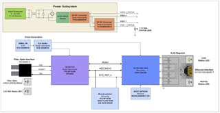
I have new design that I'm in the board bring-up phase with and I have some familiarity with the switch and this is my first design with the DP83822 PHY. The PHY is pin strapped to work in 100base-FX mode and is connected to a 100mbs 1x9 optical module.
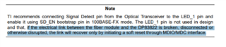
The design is using a comparator on the signal detect pin and it's working correctly as the datasheet mentions that the signal detect is active high. With no fiber connected the SD signal is 0v with the fiber connected the SD is 2.4V. The LED_0 pin is remaining high whether the fiber is connected or not.
I have access to read registers via the MDIO/MDC and I'm seeing that the bit[14] in the control register #2 0x000A is set. Bit[2] in the basic mode status register 0x0001 is never set with the fiber connected. I'm starting to look in the datasheet to see if there are any other pertinent bits I should reading to help troubleshoot this. Any advice is welcome.
The basic mode control register 0x0000 is reading 0x3100 which indicates that bit[12] is set. Should the Auto-Negotiation Enable bit be set with 100base-FX?
Any help is greatly appreciated.