This thread has been locked.

If you have a related question, please click the "Ask a related question" button in the top right corner. The newly created question will be automatically linked to this question.

DS90UB941AS-Q1: Configuration issues with chips

Part Number: DS90UB941AS-Q1


At present, our company has encountered the following issues while debugging the TI941+TI948 split screen scheme:
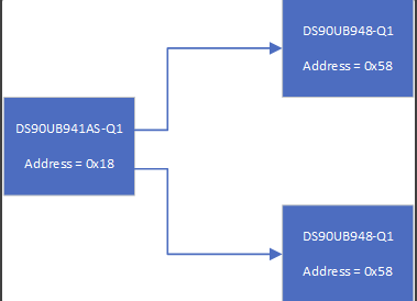
The overall block diagram is as follows:
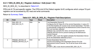
941 Configuration:

0x1E, 0x01, port0

0x03, 0x9a, pass_ Through

0x1E, 0x02, port1

0x03, 0x9a, pass_ Through

0x1E, 0x01, port0

Address 0x07, 0x58, 948

0x08, 0x5c, port0 948 address alias

0x1E, 0x02, port1

Address 0x07, 0x58, 948

0x08, 0x5e, port1 948 address alias

After attempting to configure as above, only 948 (0x2E) on port0 can be accessed, while 948 on port1 cannot be detected

May I ask if there is any issue with the above configuration? How can I debug the 948 on port1 that cannot be detected?

  • Supplementary explanation:

    1.

    As this script:

    Write 941:

    0x1E, 0x01,   select port0

    0x03, 0x9a,   i2c pass_through

    Write 948 on port0

    0x00, 0x61,   Override Address" on the DES to assign the DES on port 0 to a different physical I2C address (7bit:0x30)

    Write 941::

    0x1E, 0x02,  port1

    0x03, 0x9a,   i2c pass_through

    Configure as above:

    • Still, only 948 on port0 can be accessed


    2.

    As this script:

    Write 941:

    0x1E, 0x01,   select port0

    0x03, 0x9a,   i2c pass_through

    Write 948 on port0

    0x00, 0x61,   Override Address" on the DES to assign the DES on port 0 to a different physical I2C address (7bit:0x30)

    Write 941::

    0x1E, 0x02,  port1

    0x03, 0x9a,   i2c pass_through

    0x01, 0x01 or 0x03

    Configure as above:

    both 948 on port0 and port1 can not be accessed


    3.

    • I'm trying to read the debug register:

    Read 941:

    Port0:

    0x5a =  0x99  :bit7 is FPD-Link III Link Ready status for selected port

    Port1:

    0x5a = 0x19

    Can  me determine by 0x5a bit7 that the hardware path on port1 is faulty

    But the value read from 0x0c is 0x07 on both port0 and port1,0x0c bit4 is Link Lost Flag for selected port

  • Hi Tony,

    Port0:

    0x5a =  0x99  :bit7 is FPD-Link III Link Ready status for selected port

    Port1:

    0x5a = 0x19

    Both ports seem to think that they are transmitting single FPD-Link III on port 0. The reading from port 1 seems incorrect. Can you double check the DUAL_CTL1 register to make sure the 941AS is strapped into splitter/independent mode?

    Is the 941AS cable plugged into port 0 for both of the 948s?

    Best,

    Jack

  • 1. DUAL_ I have configured the CTL1 register on my end. 941 and two 948 are on the same small board, and there is no need to insert them. It can be confirmed that they are connected;

    2. As the addresses of the previous two 948 are the same, I am trying to modify the IDX pin of port1 948 to 0x30, which is different from the 948 0x2c on port0,

    However, currently it is still unable to communicate with 948 on port1;

    The following is my current configuration. Please help me check it. Thank you very much;

    {0x0c, 0x01, 0x02},

    {0x0c, 0x01, 0x08},

    {0x0c, 0x1e, 0x01},//port0

    {0x0c, 0x4f, 0x8c},//4lane contiune clk

    {0x0c, 0x5b, 0x07},//split mode


    {0x0c, 0x40, 0x04},//DSI/DPHY port0

    {0x0c, 0x41, 0x05},

    {0x0c, 0x42, 0x2e},//dsi clock 438,

    {0x0c, 0x41, 0x20},

    {0x0c, 0x42, 0x6f},


    {0x0c, 0x56, 0x80},//left/right split

    {0x0c, 0x32, 0x80},

    {0x0c, 0x33, 0x07},//h 1920


    {0x0c, 0x1e, 0x01},//port0

    {0x0c, 0x36, 0x00},

    {0x0c, 0x37, 0x80},

    {0x0c, 0x38, 0x7f},//stop 1919

    {0x0c, 0x39, 0x07},

    {0x0c, 0x3a, 0x00},

    {0x0c, 0x3b, 0x00},

    {0x0c, 0x3c, 0xAF},//stop 1199

    {0x0c, 0x3d, 0x04},


    {0x0c, 0x1e, 0x02},//port1

    {0x0c, 0x36, 0x00},

    {0x0c, 0x37, 0x80},

    {0x0c, 0x38, 0x7f},//stop 1919

    {0x0c, 0x39, 0x07},

    {0x0c, 0x3a, 0x00},

    {0x0c, 0x3b, 0x00},

    {0x0c, 0x3c, 0xAF},//stop 1199

    {0x0c, 0x3d, 0x04},


    {0x0c, 0x40, 0x10},

    {0x0c, 0x41, 0x86},

    {0x0c, 0x42, 0x0a},

    {0x0c, 0x41, 0x94},

    {0x0c, 0x42, 0x0a},


    {0x0c, 0x1e, 0x01},//port0

    {0x0c, 0x03, 0x9a},//pass_ Through

    {0x0c, 0x1e, 0x02},//port1

    {0x0c, 0x03, 0x9a},//pass_ Through

    {0x2c, 0x1e, 0x09},//port0 panel backlight

    {0x30, 0x1e, 0x09},//port1 panel backlight

    {0x0c, 0x01, 0x00},//enable dsi

  • Hi Tony,

    Thank you for providing the configuration sequence. Because we recommend configuring DSI settings while DSI inputs are inactive, can you swap lines 4 and 5? This won't fix the I2C issue but will ensure there aren't any errors for video setup.

    Can you confirm that the output of the 941AS goes into port 0 for both of the 948 devices? I want to make sure the hardware configuration is correct.

    Because the IDX pins are now modified to provide a different address, can you check the port 0 and port 1 values after the 941 is configured. This will let us know if the 941 is correctly reading the 948 configuration for both devices.

    Best,

    Jack

  • 1. Currently, we have configured the i2c of 948 on port 1 separately to address the issue of communication issues with 948 on port 1. Currently, it is preliminary to see that both channels of 948 can be locked, but according to the attachment "941+948. txt", the configuration cannot be lit. Can you help check;


    2. Attempted to use internal timing and clk of 941 for pattern testing, but no images were produced. Attached file "941_ Pattern. bat "is my test script. Is there a problem with this configuration validation? And what good methods are there to locate which part of the problem is?

    941_ Patterns The specific content of bat is as follows:

    #!/bin/sh

    adb shell i2cset -fy 1 0x0c 0x01 0x08 b
    adb shell i2cset -fy 1 0x0c 0x01 0x02 b

    adb shell i2cset -fy 1 0x0c 0x5b 0x01 b
    adb shell i2cset -fy 1 0x0c 0x1e 0x01 b
    adb shell i2cset -fy 1 0x0c 0x03 0x9a b
    adb shell i2cset -fy 1 0x2c 0x1e 0x09 b
    ::adb shell i2cset -fy 2 0x30 0x1e 0x09 b

    adb shell i2cset -fy 1 0x0c 0x01 0x00 b
    adb shell i2cset -fy 1 0x0c 0x06 0x01 b
    adb shell i2cset -fy 1 0x0c 0x56 0x01 b


    adb shell i2cset -fy 1 0x0c 0x40 0x04 b
    adb shell i2cset -fy 1 0x0c 0x41 0x21 b
    adb shell i2cset -fy 1 0x0c 0x42 0x60 b
    adb shell i2cset -fy 1 0x0c 0x40 0x04 b
    adb shell i2cset -fy 1 0x0c 0x41 0x05 b
    adb shell i2cset -fy 1 0x0c 0x42 0x32 b


    adb shell i2cset -fy 1 0x0c 0x66 0x03 b
    ::adb shell i2cset -fy 1 0x0c 0x67 0x19 b
    adb shell i2cset -fy 1 0x0c 0x67 0x02 b

    adb shell i2cset -fy 1 0x0c 0x66 0x04 b
    ::adb shell i2cset -fy 1 0x0c 0x67 0xD0 b
    adb shell i2cset -fy 1 0x0c 0x67 0x20 b

    adb shell i2cset -fy 1 0x0c 0x66 0x05 b
    ::adb shell i2cset -fy 1 0x0c 0x67 0xD7 b
    adb shell i2cset -fy 1 0x0c 0x67 0xB8 b

    adb shell i2cset -fy 1 0x0c 0x66 0x06 b
    adb shell i2cset -fy 1 0x0c 0x67 0x4D b

    adb shell i2cset -fy 1 0x0c 0x66 0x07 b
    adb shell i2cset -fy 1 0x0c 0x67 0x80 b

    adb shell i2cset -fy 1 0x0c 0x66 0x08 b
    adb shell i2cset -fy 1 0x0c 0x67 0x07 b

    adb shell i2cset -fy 1 0x0c 0x66 0x09 b
    adb shell i2cset -fy 1 0x0c 0x67 0x4b b


    adb shell i2cset -fy 1 0x0c 0x66 0x0a b
    ::adb shell i2cset -fy 1 0x0c 0x67 0x0a b
    adb shell i2cset -fy 1 0x0c 0x67 0x14 b

    adb shell i2cset -fy 1 0x0c 0x66 0x0b b
    adb shell i2cset -fy 1 0x0c 0x67 0x04 b

    adb shell i2cset -fy 1 0x0c 0x66 0x0c b
    ::adb shell i2cset -fy 1 0x0c 0x67 0x06 b
    adb shell i2cset -fy 1 0x0c 0x67 0x0C b

    adb shell i2cset -fy 1 0x0c 0x66 0x0d b
    adb shell i2cset -fy 1 0x0c 0x67 0x14 b

    adb shell i2cset -fy 1 0x0c 0x66 0x0e b
    adb shell i2cset -fy 1 0x0c 0x67 0x0F b

    adb shell i2cset -fy 1 0x0c 0x65 0x05 b
    adb shell i2cset -fy 1 0x0c 0x64 0x53 b

  • Hi Tony,

    1. Currently, we have configured the i2c of 948 on port 1 separately to address the issue of communication issues with 948 on port 1. Currently, it is preliminary to see that both channels of 948 can be locked, but according to the attachment "941+948. txt", the configuration cannot be lit. Can you help check;

    Did setting the IDx of the 948 on port 1 fix the communications I2C issue? What addresses are the 948 on Port 0 and Port 1 set to?

    2. Attempted to use internal timing and clk of 941 for pattern testing, but no images were produced. Attached file "941_ Pattern. bat "is my test script. Is there a problem with this configuration validation? And what good methods are there to locate which part of the problem is?

    What is the video timing you are trying to configure for the PATGEN? In your script you are writing to 0x67 twice sometimes. The PATGEN indirect access registers have no auto-increment function.

    Also according to your script you are configuring the 941 to operate in FPD TX Port 0 only. Are you wanting to see Pattern output on both 948s?

    Regards,

    Jack

  • 1. The address of 948 on port1 is 0x30, the address of 948 on port0 is 0x2c, and the 948 on port1 is controlled by a single i2c, and port0 is controlled by 941 transparent transmission

    2. Screen timing is as follows: dual link lvds screen

    3. 0x67 is not written twice in the script. The two colons of "::" indicate that the line has been commented.

    4.The script wants to verify that 948 on port0 can be displayed first and then proceed to the next step of verification, but currently no single port can be verified and displayed, and finally 948 on both ports can be displayed;

    According to the relevant situation, what other suggestions? Thank you!

  • Hi Tony,

    Thank you for clarifying on the code.

    4.The script wants to verify that 948 on port0 can be displayed first and then proceed to the next step of verification, but currently no single port can be verified and displayed, and finally 948 on both ports can be displayed;

    So the 941 output works with outputting to both 948s? When the 941 is operating using a superframe input, it is expecting to output on both ports. Forcing the 941 into single output mode is not expected when using superframe input.

    Regards,

    Jack

  • Our soc is to configure the super frame output to 941,941 and cut the output to two-channel 948. However, based on the configuration in the attachment 941+948.txt, it cannot be lit. Therefore, we try to use 941 internal timing and clk to paatern to verify the channel problem.

    The attached 941_pattern_bat.txt uses 941 internal timing and clk pattern to verify the hardware path between 941 and the screen. In order to verify the upper path of port0, the script only configurates port0, which does not depend on soc output. The current problem is not only the display output using soc source input, but also the 941 internal timing and clk pattern. Please read my previous email carefully, and please help to check the configuration or provide the debug method

    The attachment "941+948.txt" is a normal configuration using soc source for cutting output

    The attachment "941_pattern_bat.txt" uses 941 internal timing and clk to verify the configuration of port0 upper path.

    "941+948" is as follows:

    {0x0c, 0x01, 0x02},
        {0x0c, 0x01, 0x08},
        {0x0c, 0x1e, 0x01},     //port0
        {0x0c, 0x5b, 0x07},  //split mode
        {0x0c, 0x4f, 0x8c},  //4lane contiune clk
        {0x0c, 0x02, 0x06},  //data clk PN swap

        {0x0c, 0x40, 0x04},  //DSI/DPHY port0
        {0x0c, 0x41, 0x05},
        {0x0c, 0x42, 0x2e},  //dsi clock 438,
        {0x0c, 0x41, 0x20},
        {0x0c, 0x42, 0x6f},

        {0x0c, 0x56, 0x80}, //left/right split
        {0x0c, 0x32, 0x80},
        {0x0c, 0x33, 0x07}, //h 1920

        {0x0c, 0x1e, 0x01},  //port0
        {0x0c, 0x36, 0x00},
        {0x0c, 0x37, 0x80},
        {0x0c, 0x38, 0x7f},  //stop 1919
        {0x0c, 0x39, 0x07},
        {0x0c, 0x3a, 0x00},
        {0x0c, 0x3b, 0x00},
        {0x0c, 0x3c, 0xAF},  //stop 1199
        {0x0c, 0x3d, 0x04},
        
        {0x0c, 0x1e, 0x02},  //port1
        {0x0c, 0x36, 0x00},
        {0x0c, 0x37, 0x80},
        {0x0c, 0x38, 0x7f},  //stop 1919
        {0x0c, 0x39, 0x07},
        {0x0c, 0x3a, 0x00},
        {0x0c, 0x3b, 0x00},
        {0x0c, 0x3c, 0xAF},  //stop 1199
        {0x0c, 0x3d, 0x04},

        {0x0c, 0x40, 0x10},  //DSI/DPHY port1
        {0x0c, 0x41, 0x86},
        {0x0c, 0x42, 0x0a},
        {0x0c, 0x41, 0x94},
        {0x0c, 0x42, 0x0a},
        
        {0x0c, 0x1e, 0x01},     //port0
        {0x0c, 0x03, 0x9a},  //pass_through
        {0x0c, 0x1e, 0x02},     //port1
        {0x0c, 0x03, 0x9a},  //pass_through
        {0x2c, 0x1e, 0x09},  //port0 panel backlight
        {0x30, 0x34, 0x19},
        {0x30, 0x1e, 0x09},  //port1 panel backlight
        {0x0c, 0x01, 0x00},  //enable dsi

    “941_pattern_bat "The contents are as follows:

    #!/bin/sh

    adb shell i2cset -fy 1 0x0c 0x01 0x08 b
    adb shell i2cset -fy 1 0x0c 0x01 0x02 b

    adb shell i2cset -fy 1 0x0c 0x5b 0x01 b
    adb shell i2cset -fy 1 0x0c 0x1e 0x01 b
    adb shell i2cset -fy 1 0x0c 0x03 0x9a b
    adb shell i2cset -fy 1 0x2c 0x1e 0x09 b
    ::adb shell i2cset -fy 2 0x30 0x1e 0x09 b

    adb shell i2cset -fy 1 0x0c 0x01 0x00 b
    adb shell i2cset -fy 1 0x0c 0x06 0x01 b
    adb shell i2cset -fy 1 0x0c 0x56 0x01 b


    adb shell i2cset -fy 1 0x0c 0x40 0x04 b
    adb shell i2cset -fy 1 0x0c 0x41 0x21 b
    adb shell i2cset -fy 1 0x0c 0x42 0x60 b
    adb shell i2cset -fy 1 0x0c 0x40 0x04 b
    adb shell i2cset -fy 1 0x0c 0x41 0x05 b
    adb shell i2cset -fy 1 0x0c 0x42 0x32 b


    adb shell i2cset -fy 1 0x0c 0x66 0x03 b
    ::adb shell i2cset -fy 1 0x0c 0x67 0x19 b
    adb shell i2cset -fy 1 0x0c 0x67 0x02 b

    adb shell i2cset -fy 1 0x0c 0x66 0x04 b
    ::adb shell i2cset -fy 1 0x0c 0x67 0xD0 b
    adb shell i2cset -fy 1 0x0c 0x67 0x20 b

    adb shell i2cset -fy 1 0x0c 0x66 0x05 b
    ::adb shell i2cset -fy 1 0x0c 0x67 0xD7 b
    adb shell i2cset -fy 1 0x0c 0x67 0xB8 b

    adb shell i2cset -fy 1 0x0c 0x66 0x06 b
    adb shell i2cset -fy 1 0x0c 0x67 0x4D b

    adb shell i2cset -fy 1 0x0c 0x66 0x07 b
    adb shell i2cset -fy 1 0x0c 0x67 0x80 b

    adb shell i2cset -fy 1 0x0c 0x66 0x08 b
    adb shell i2cset -fy 1 0x0c 0x67 0x07 b

    adb shell i2cset -fy 1 0x0c 0x66 0x09 b
    adb shell i2cset -fy 1 0x0c 0x67 0x4b b


    adb shell i2cset -fy 1 0x0c 0x66 0x0a b
    ::adb shell i2cset -fy 1 0x0c 0x67 0x0a b
    adb shell i2cset -fy 1 0x0c 0x67 0x14 b

    adb shell i2cset -fy 1 0x0c 0x66 0x0b b
    adb shell i2cset -fy 1 0x0c 0x67 0x04 b

    adb shell i2cset -fy 1 0x0c 0x66 0x0c b
    ::adb shell i2cset -fy 1 0x0c 0x67 0x06 b
    adb shell i2cset -fy 1 0x0c 0x67 0x0C b

    adb shell i2cset -fy 1 0x0c 0x66 0x0d b
    adb shell i2cset -fy 1 0x0c 0x67 0x14 b

    adb shell i2cset -fy 1 0x0c 0x66 0x0e b
    adb shell i2cset -fy 1 0x0c 0x67 0x0F b

    adb shell i2cset -fy 1 0x0c 0x65 0x05 b
    adb shell i2cset -fy 1 0x0c 0x64 0x53 b

  • Hi Tony,

    I made the following changes to "941_pattern_bat.txt"

    • Changed BRIDGE_CFG2 to clock the FPD3 transmitter on the internal reference clock. Before it was using the external reference clock
    • Changed the internal PCLK to be 154.8 MHz by setting M = 6 and N = 31. The internal PCLK before was set too slow to 100 MHz.

    Best

    Jack

    adb shell i2cset -fy 1 0x0c 0x01 0x0a b 
    
    adb shell i2cset -fy 1 0x0c 0x5b 0x01 b 
    adb shell i2cset -fy 1 0x0c 0x1e 0x01 b 
    adb shell i2cset -fy 1 0x0c 0x03 0x9a b 
    adb shell i2cset -fy 1 0x2c 0x1e 0x09 b 
    ::adb shell i2cset -fy 2 0x30 0x1e 0x09 b 
    
    adb shell i2cset -fy 1 0x0c 0x01 0x00 b 
    adb shell i2cset -fy 1 0x0c 0x06 0x01 b 
    adb shell i2cset -fy 1 0x0c 0x56 0x02 b 
    
    
    adb shell i2cset -fy 1 0x0c 0x40 0x04 b
    adb shell i2cset -fy 1 0x0c 0x41 0x21 b
    adb shell i2cset -fy 1 0x0c 0x42 0x60 b
    adb shell i2cset -fy 1 0x0c 0x40 0x04 b
    adb shell i2cset -fy 1 0x0c 0x41 0x05 b
    adb shell i2cset -fy 1 0x0c 0x42 0x32 b
    
    
    adb shell i2cset -fy 1 0x0c 0x66 0x03 b 
    ::adb shell i2cset -fy 1 0x0c 0x67 0x19 b 
    adb shell i2cset -fy 1 0x0c 0x67 0x1F b
    
    adb shell i2cset -fy 1 0x0c 0x66 0x1A b 
    adb shell i2cset -fy 1 0x0c 0x67 0x06 b
    
    adb shell i2cset -fy 1 0x0c 0x66 0x04 b
    ::adb shell i2cset -fy 1 0x0c 0x67 0xD0 b
    adb shell i2cset -fy 1 0x0c 0x67 0x20 b
    
    adb shell i2cset -fy 1 0x0c 0x66 0x05 b
    ::adb shell i2cset -fy 1 0x0c 0x67 0xD7 b
    adb shell i2cset -fy 1 0x0c 0x67 0xB8 b
    
    adb shell i2cset -fy 1 0x0c 0x66 0x06 b
    adb shell i2cset -fy 1 0x0c 0x67 0x4D b
    
    adb shell i2cset -fy 1 0x0c 0x66 0x07 b
    adb shell i2cset -fy 1 0x0c 0x67 0x80 b
    
    adb shell i2cset -fy 1 0x0c 0x66 0x08 b
    adb shell i2cset -fy 1 0x0c 0x67 0x07 b
    
    adb shell i2cset -fy 1 0x0c 0x66 0x09 b
    adb shell i2cset -fy 1 0x0c 0x67 0x4b b
    
    
    adb shell i2cset -fy 1 0x0c 0x66 0x0a b
    ::adb shell i2cset -fy 1 0x0c 0x67 0x0a b
    adb shell i2cset -fy 1 0x0c 0x67 0x14 b
    
    adb shell i2cset -fy 1 0x0c 0x66 0x0b b
    adb shell i2cset -fy 1 0x0c 0x67 0x04 b
    
    adb shell i2cset -fy 1 0x0c 0x66 0x0c b
    ::adb shell i2cset -fy 1 0x0c 0x67 0x06 b
    adb shell i2cset -fy 1 0x0c 0x67 0x0C b
    
    adb shell i2cset -fy 1 0x0c 0x66 0x0d b
    adb shell i2cset -fy 1 0x0c 0x67 0x14 b
    
    adb shell i2cset -fy 1 0x0c 0x66 0x0e b
    adb shell i2cset -fy 1 0x0c 0x67 0x0F b
    
    adb shell i2cset -fy 1 0x0c 0x65 0x05 b
    adb shell i2cset -fy 1 0x0c 0x64 0x53 b
    
    adb shell i2cset -fy 1 0x0c 0x01 0x00 b 

  • 1. The configuration of BRIDGE_CFG2 is set to 0x80(LEFT_RIGHT_3D) when soc source is used normally, and 0x02(internal reference clock mode) when pattern is used in 941 internal clk. Is this OK?

    2. 948 cannot be locked after Set M=6 and N=31, so 948 on port0 cannot be displayed, but 948 can be locked when M=1 and N=2 are configured, and the screen has consulted panel fae to support 30fps. In theory, 100M pclk is fine

    The modified sprict is as follows:

    #!/bin/sh

    adb shell i2cset -fy 1 0x0c 0x01 0x08 b
    adb shell i2cset -fy 1 0x0c 0x01 0x02 b

    adb shell i2cset -fy 1 0x0c 0x5b 0x01 b
    adb shell i2cset -fy 1 0x0c 0x1e 0x01 b
    adb shell i2cset -fy 1 0x0c 0x03 0x9a b
    adb shell i2cset -fy 1 0x2c 0x1e 0x09 b

    adb shell i2cset -fy 1 0x0c 0x01 0x00 b
    adb shell i2cset -fy 1 0x0c 0x06 0x01 b
    adb shell i2cset -fy 1 0x0c 0x56 0x02 b    //内部参考时钟模式


    adb shell i2cset -fy 1 0x0c 0x40 0x04 b
    adb shell i2cset -fy 1 0x0c 0x41 0x21 b
    adb shell i2cset -fy 1 0x0c 0x42 0x60 b
    adb shell i2cset -fy 1 0x0c 0x40 0x04 b
    adb shell i2cset -fy 1 0x0c 0x41 0x05 b
    adb shell i2cset -fy 1 0x0c 0x42 0x32 b


    adb shell i2cset -fy 1 0x0c 0x66 0x03 b
    adb shell i2cset -fy 1 0x0c 0x67 0x1F b   //set N=31
    ::adb shell i2cset -fy 1 0x0c 0x67 0x02 b

    adb shell i2cset -fy 1 0x0c 0x66 0x04 b
    adb shell i2cset -fy 1 0x0c 0x67 0x20 b

    adb shell i2cset -fy 1 0x0c 0x66 0x05 b
    adb shell i2cset -fy 1 0x0c 0x67 0xB8 b

    adb shell i2cset -fy 1 0x0c 0x66 0x06 b
    adb shell i2cset -fy 1 0x0c 0x67 0x4D b

    adb shell i2cset -fy 1 0x0c 0x66 0x07 b
    adb shell i2cset -fy 1 0x0c 0x67 0x80 b

    adb shell i2cset -fy 1 0x0c 0x66 0x08 b
    adb shell i2cset -fy 1 0x0c 0x67 0x07 b

    adb shell i2cset -fy 1 0x0c 0x66 0x09 b
    adb shell i2cset -fy 1 0x0c 0x67 0x4b b


    adb shell i2cset -fy 1 0x0c 0x66 0x0a b
    adb shell i2cset -fy 1 0x0c 0x67 0x14 b

    adb shell i2cset -fy 1 0x0c 0x66 0x0b b
    adb shell i2cset -fy 1 0x0c 0x67 0x04 b

    adb shell i2cset -fy 1 0x0c 0x66 0x0c b
    adb shell i2cset -fy 1 0x0c 0x67 0x0C b

    adb shell i2cset -fy 1 0x0c 0x66 0x0d b
    adb shell i2cset -fy 1 0x0c 0x67 0x14 b

    adb shell i2cset -fy 1 0x0c 0x66 0x0e b
    adb shell i2cset -fy 1 0x0c 0x67 0x0F b

    adb shell i2cset -fy 1 0x0c 0x66 0x1a b
    adb shell i2cset -fy 1 0x0c 0x67 0x06 b  //set M=6

    adb shell i2cset -fy 1 0x0c 0x65 0x05 b
    adb shell i2cset -fy 1 0x0c 0x64 0x53 b

  • Hi Tony,

    1. The configuration of BRIDGE_CFG2 is set to 0x80(LEFT_RIGHT_3D) when soc source is used normally, and 0x02(internal reference clock mode) when pattern is used in 941 internal clk. Is this OK?

    This is OK. When the SOC source is used, the 941 will be using to DSI clock to generate the FPD signal. When the 941 PATGEN is used, the internal timing will generate the FPD signal.

    2. 948 cannot be locked after Set M=6 and N=31, so 948 on port0 cannot be displayed, but 948 can be locked when M=1 and N=2 are configured, and the screen has consulted panel fae to support 30fps. In theory, 100M pclk is fine

    Sounds good. I based my M and N values off of the panel datasheet. If the panel can successfully the pattern, the PATGEN is good.

    Best,

    Jack

  • Sounds good. I based my M and N values off of the panel datasheet. If the panel can successfully the pattern, the PATGEN is good

    But M=1 and N=2, the screen is still black.

  • Hi Hongwu,

    Lock wasn't acquired with the M=6 and N=31 because the PCLK was set too high for single link. I adjusted the M and N values for a 30 FPS PCLK and tested this with a 941 and 948 to make sure that it would lock. Because the screen is designed for 60 FPS, I'm not sure if the screen will display correctly.

    Current PATGEN settings:

    • M = 5
    • N = 56
    • PCLK = 71.4 MHz

    adb shell i2cset -fy 1 0x0c 0x01 0x0a b 
    
    adb shell i2cset -fy 1 0x0c 0x5b 0x01 b 
    adb shell i2cset -fy 1 0x0c 0x1e 0x01 b 
    adb shell i2cset -fy 1 0x0c 0x03 0x9a b 
    adb shell i2cset -fy 1 0x2c 0x1e 0x09 b 
    ::adb shell i2cset -fy 2 0x30 0x1e 0x09 b 
    
    adb shell i2cset -fy 1 0x0c 0x01 0x00 b 
    adb shell i2cset -fy 1 0x0c 0x06 0x01 b 
    adb shell i2cset -fy 1 0x0c 0x56 0x02 b 
    
    
    adb shell i2cset -fy 1 0x0c 0x40 0x04 b
    adb shell i2cset -fy 1 0x0c 0x41 0x21 b
    adb shell i2cset -fy 1 0x0c 0x42 0x60 b
    adb shell i2cset -fy 1 0x0c 0x40 0x04 b
    adb shell i2cset -fy 1 0x0c 0x41 0x05 b
    adb shell i2cset -fy 1 0x0c 0x42 0x32 b
    
    
    adb shell i2cset -fy 1 0x0c 0x66 0x03 b 
    ::adb shell i2cset -fy 1 0x0c 0x67 0x19 b 
    adb shell i2cset -fy 1 0x0c 0x67 0x38 b
    
    adb shell i2cset -fy 1 0x0c 0x66 0x1A b 
    adb shell i2cset -fy 1 0x0c 0x67 0x05 b
    
    adb shell i2cset -fy 1 0x0c 0x66 0x04 b
    ::adb shell i2cset -fy 1 0x0c 0x67 0xD0 b
    adb shell i2cset -fy 1 0x0c 0x67 0x20 b
    
    adb shell i2cset -fy 1 0x0c 0x66 0x05 b
    ::adb shell i2cset -fy 1 0x0c 0x67 0xD7 b
    adb shell i2cset -fy 1 0x0c 0x67 0xB8 b
    
    adb shell i2cset -fy 1 0x0c 0x66 0x06 b
    adb shell i2cset -fy 1 0x0c 0x67 0x4D b
    
    adb shell i2cset -fy 1 0x0c 0x66 0x07 b
    adb shell i2cset -fy 1 0x0c 0x67 0x80 b
    
    adb shell i2cset -fy 1 0x0c 0x66 0x08 b
    adb shell i2cset -fy 1 0x0c 0x67 0x07 b
    
    adb shell i2cset -fy 1 0x0c 0x66 0x09 b
    adb shell i2cset -fy 1 0x0c 0x67 0x4b b
    
    
    adb shell i2cset -fy 1 0x0c 0x66 0x0a b
    ::adb shell i2cset -fy 1 0x0c 0x67 0x0a b
    adb shell i2cset -fy 1 0x0c 0x67 0x14 b
    
    adb shell i2cset -fy 1 0x0c 0x66 0x0b b
    adb shell i2cset -fy 1 0x0c 0x67 0x04 b
    
    adb shell i2cset -fy 1 0x0c 0x66 0x0c b
    ::adb shell i2cset -fy 1 0x0c 0x67 0x06 b
    adb shell i2cset -fy 1 0x0c 0x67 0x0C b
    
    adb shell i2cset -fy 1 0x0c 0x66 0x0d b
    adb shell i2cset -fy 1 0x0c 0x67 0x14 b
    
    adb shell i2cset -fy 1 0x0c 0x66 0x0e b
    adb shell i2cset -fy 1 0x0c 0x67 0x0F b
    
    adb shell i2cset -fy 1 0x0c 0x65 0x05 b
    adb shell i2cset -fy 1 0x0c 0x64 0x53 b
    
    adb shell i2cset -fy 1 0x0c 0x01 0x00 b 

    Best,

    Jack