This thread has been locked.

If you have a related question, please click the "Ask a related question" button in the top right corner. The newly created question will be automatically linked to this question.

THVD2450: idle bus failsafe issue

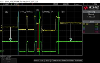
Part Number: THVD2450
Other Parts Discussed in Thread: ISO1450, , THVD1550, THVD1450, THVD1424

Hi,

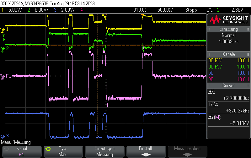
I am using the THVD2450DRBR at a 1-to-1 RS485 connection. The receiving part is an ISO1450, both ends terminated with 120R, cable length around 4m, 10Mbit bitrate. Usually the THVD2450 sends a message and the ISO1450 replies to it. However, I have seen cases where during the bus turnaround - when the bus is idle - the R output on the THVD2450 goes low where it should be high according to the datasheet.


Yellow: Pin A, Green: Pin R

The idle bus detection before and after the Message works fine.

  • Only the differential bus voltage matters. Please tell the oscilloscope to compute A−B.

  • 1:A, 2: B F1: B-A, 3V/Div, 3: R

    Can't really spot a difference between Before/after the message and bus turn around

  • Hi Stefan,

    Can you decrease the V/Div to like 1 or 500mV and just show when the bus is idle. Right now it looks like we are at 5V/div and it looks like there could be some movement of the waveform. 

    This device isn't like most of our THVD devices with its fail-safe - in general I would consider it worse because its not really failsafe because there is undefined regions of receiver inputs on this device - true fail-safe devices don't have that issue. Essentially this device is fail-safe if it stays between -40mV and 40mV for a delay period - if it goes out of that range - its not longer fail-safe. So any noise could mess up the bus - that is why I am wanting to see the differential signal  closer and with less V/div because noise could be an issue.

    Second - if you have a schematic that would be very helpful - if the only thing on the bus is the termination resistors, you can just let me know - but if there are other passives please let me know as this can add extra variables to bus performance?  

    Finally - why did you choose this THVD device? I ask because most of our other THVD devices have what I would argue better fail-safes (both VIT+ and VIT- are less than 0V - meaning by default open, idle, and short bus conditions are read as high - where this device there is a delay and if you have noise on the bus it can really mess things up. 

    Please let me know!

    Best,

    Parker Dodson

  • Hi Parker,

    thanx for your explanation, please find attached the Bus Idle with 200mV/Div. Be aware that I had so solder some short leads for the scope to the termination R so that there as some small stubs which might mess up the measurement.


    The only thing on the bus are the 120R resistors, the two devices are connected via a Mini-IO cable by TE. We have chosen the 2450 as we wanted to have a high fault protection and this device was available at the time were design the PCB. Before fitting the 2450 we have be using the MAX14770 (which is a true failsafe device) and the connection was running without problems.


    I also did a test with some weak 1K failsafe resistors on A/B to VCC/GND and the problem disappeared. I guess your explanation about the noise could mess up the bus idle is correct. Unfortunately we cannot wait 10us or so until the device enters the failsafe detection.

    If this device is not the first choice for our application what would you recommend? (3.5-5V, >= 20Mbit, high fault protection)

  • Hi Stefan,

    So yes - it looks like based on your test and previous results - this is an issue with how the idle fail-safe works for this device.

    That being said - do you need the full 70V fault tolerance range? As all of our +/-70V fault tolerant devices either have the non-ideal fail-safe or are not fast enough.

    Something like the THVD1450 has higher fault tolerance than the MAX device you were using but it is only at +/-18V - but it does have a true fail-safe. The THVD1550 is a more cost effective version of the THVD1450 but it only works at 5V compared to the wide 3.3V to 5V range of the THVD1450. I will say our THVD14xx family of devices is a very solid choice for many applications - but it does have the draw back of not as high of a fault tolerance.

    Please let me know on the needed fault range - because we do have some options but they won't be as robust as the THVD2450. Or the other option is adding a pair of idle fail-safe resistors (for two devices on bus 680 Ohms is ideal for idle fail-safe - with the termination by the 680 Ohm fail-safe resistors being placed at around 131 Ohms to make the nodes equivalent impedance as 120 Ohms) would also protect in cases of idle bus - we do have a note if you want to go through the derivations yourself  -  https://www.ti.com/lit/an/slyt324/slyt324.pdf  - but I do think these are our best options that we can offer at the moment.

    Best,

    Parker Dodson

  • Hi Parker,

    the 70V fault tolerance is rather a 'wish' than a 'must'. We have seen cases where during commission the input was wired wrongly to our power line, 24VDC - which of course damaged the board with the MAX. 

    However as functionality has got priority over commission issues, I am going to replace the 2540 by the suggested 1450 which is already been used in other projects even when it can't cope with 24V. Fitting failsafe resistors for the 2540 would require a new PCB layout. If a new PCB is gong to be made in the future I'd probably rather switch to a more universal device such as the THVD1424 (with some no fit failsafe resistors - just in case)

    Thanks a lot your your help.

    Regards

    Stefan