This thread has been locked.

If you have a related question, please click the "Ask a related question" button in the top right corner. The newly created question will be automatically linked to this question.

DS160PR810EVM-RSC: End device detection

Part Number: DS160PR810EVM-RSC
Other Parts Discussed in Thread: USB2ANY, DS160PR810, DS160PR410

Hello Team,

We have some queries to be resolved related to End device detection.

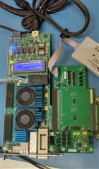
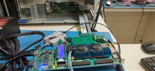
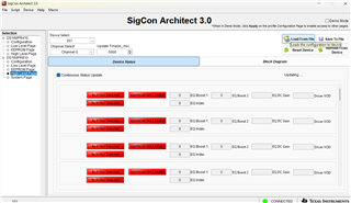
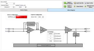
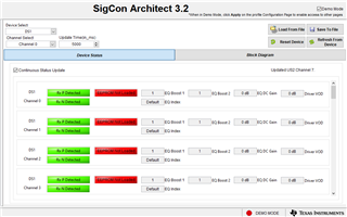
-> Trying to connect Root complex(HP Server) to any Dev Kit(End device) / to PAC card through Redriver EVB.

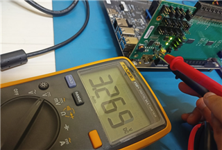
-> We are unable to detect the end device through PCIe connection. We have verified all headers on the EV board and accordingly set the jumpers.

Request your support, to quickly solve the issue.

Thanks

  • hi,

    We were able to set the jumpers and get the end device detected for Gen 3. We have also programmed the A10 Dev Kit connected to Server via redriver (DS160PR810EVM). Currently we have the issue in detecting the RX Channel and load from EEPROM to get the gain details (please check the screenshot below).

    can you advice how to get over this? 

    Best Rgds,
    Felix

  • Hi Sandhya,

    As I understand there seems to be an issue with the RX detection? Here are some ideas:

    • Can you force the system into PCIe Gen 1 and see if the detection works?
    • Can you connect the endpoint directly to the root complex and see if the detection works?
    • What mode is the EVM being run in? I2C or pin mode?
    • Is the EVM properly powered on? Several power LEDs should light up and you should be able to communicate with it using a USB2ANY/Aardvark connection and our SigCon Architect software if you are in I2C mode.

    Best,

    Evan Su

  • Hi Evan Su,

     Here, the inline the response:

                Can you force the system into PCIe Gen 1 and see if the detection works?

    • When we are forcing the system into Gen 1, we can able to detect the device which is connected to the END point of the EVM.Currently we have the issue in detecting the RX Channel and load from EEPROM .Can you connect the endpoint directly to the root complex and see if the detection works?
    • Yes.

      What mode is the EVM being run in? I2C or pin mode?
    • We tried in both Modes. In I2C mode, i can able to write the data to EEPROM but, In pin mode i can't able to write to EEPROM.

      Is the EVM properly powered on? Several power LEDs should light up and you should be able to communicate with it using a USB2ANY/Aardvark connection and our SigCon Architect software if you are in I2C mode.
    • Yes. In Pin mode, all the LEDs which are connected to buffer gate are turning ON but In I2C mode, The LED which is connected to ALL_DONE_N pin is not turning ON. Even though LED is OFF in I2C mode, able to communicate with the card.

    Regards,
    Sandhya

  • Hi Sandhya,

    Thanks for the observations, I see now that the issue is from the EVM's point of view. I am wondering if something is preventing the devices from communicating with the primary I2C bus, and then the GUI will assume that no RX is detected, no EEPROM is loaded, etc. Can you tell me if these EQ values ever load into the GUI if you wait?

    You can also share a picture of the EVM with us so we can examine the components and jumper settings.

    Best,

    Evan Su

  • hi Evan,

    Here is the setup:

    Pin mode:

    I2C mode:

    Total Setup:

  • Hello Evan,

    Even if we wait , the EQ values were never loaded into GUI.

    Regards
    sandhya

  • Hi Sandhya and Poh Kok,

    Thanks for the information, I will review it. If the EQ values never load then it is more evidence suggesting that there is some communication issue on the board. I have not experienced this myself when using similar EVMs so I will check with my team.

    Best,

    Evan Su

  • Hi Evan,

    Any updates from the Team?

    Regards
    Sandhya

  • Hi Sandhya,

    Can you check the setting of jumper J4 (powerdown control, must be shunted PWDN --> GND in all operating modes)? It should be to the right of the USB2ANY connection header, I cannot see what it is configured to in the images provided.

    Best,

    Evan Su

  • Hello Evan,

    Jumper J4 is connected to PWDN --> GND in all operating modes.

    Regards
    Sandhya

  • Hi Sandhya,

    Thanks for verifying. So what I have seen so far is that the address pins are configured correctly (doubly so because the software did not complain about an invalid address), the devices are powered on and configured to I2C mode, and the other jumper settings look correct.

    I have two more questions:

    • I noticed that the full connector width is not being used. Is your application PCIe x8? If you scroll down on the Device Status page, do all of the channels uniformly say no RX detected, EEPROM not loaded, etc.?
    • Can you carefully read the voltage on jumper J13 when the EVM is powered up? This will help check if the EVM's power supply is working properly.

    Best,

    Evan Su

  • Hello Evan,

    • I noticed that the full connector width is not being used. Is your application PCIe x8? If you scroll down on the Device Status page, do all of the channels uniformly say no RX detected, EEPROM not loaded, etc.?

                Even we are using full connector width the output is same. We are using both x8 and x16 but, in both cases am not able to detect the signals. Yes,                    when we connect the end device all of the channels uniformly says No RX is detected and EEPROM not loaded.

    • Can you carefully read the voltage on jumper J13 when the EVM is powered up? This will help check if the EVM's power supply is working properly.

                Alright, should I check the voltage on jumper J13 while the EVM is powered up, regardless of whether the end device is connected or not?

    Regards,
    Sandhya

  • Hello Evan,

    • Can you carefully read the voltage on jumper J13 when the EVM is powered up? This will help check if the EVM's power supply is working properly.

                Voltage value on jumper J13 is 3.27V. 

    Regards,
    Sandhya          

  • Hi Sandhya,

    That voltage should be fine. As far as I can tell, the board is generally operating as expected and because your screen says "Connected" at the lower right, the devices must be active on the I2C bus. It is possible that the RX detection and EEPROM not loaded messages are just software bugs.

    There are some details we can check to determine if the devices are communicable and operating correctly. Can you navigate to the "Low Level Page" on the DS160PR810 profile and press the "Read All" button? This will force the software to try reading from all the devices over I2C. If the register values load, then you can use the "Save Config" button to export the values to a file and upload it as an attachment here for me to check. If they do not load, does the GUI report any errors?

    Best,

    Evan Su

  • Hello Evan, 

    https://lightspeedphotonics-my.sharepoint.com/:u:/p/design/EbtPscs6z05InV4cjq7WLAMBI86sL5zG2CMp5W4HETHlpw?e=cagI9A please find the config file in the provided link. The values are loading and not showing errors but still, am not able to detect any signals. Please check the config file and let me know if there is any problem.

    Thanks,
    Sandhya

  • Hi Sandhya,

    Thanks for collecting the register information. I investigated the EEPROM and RX detection registers in the DS160PR810 profile and saw some strange differences compared to the profiles of similar devices, so tomorrow I will check them against our internal register map to determine if the EEPROM and RX detection are actually working. What is interesting is that I can read the values of the DC gain and driver VOD, which from your screenshots did not load properly into the GUI.

    In the meantime, I would like to clarify to what extent the EVM is functioning from a signal perspective.

    • Poh Kok said earlier that when the system is set to Gen 1, it is possible for the system to detect the endpoint through the EVM. Is it correct that the system cannot detect the endpoint through the EVM at Gen 4 speeds?
      • This is an indicator of how the RX detection is functioning
    • When a successful detection and PCIe link through the EVM is possible, in I2C mode you may try going to the High Level Page --> Block Diagram, configure the Device Select to "All Devices", change the EQ index to 15 (maximum), and see if the PCIe link drops
      • This is an indicator of how the device drivers and output path are functioning

    Best,

    Evan Su

  • Hello Evan,

    • We are connecting the Arria10 Dev kit as END device which is GEN 3 . We are able to detect the device through EVM.
    • In high level page, whether the EQ INDEX and Gain level is max. or min in both cases the result is same. 

    And i have one query, if i won't able to detect any RX signals from the beginning how it'll show the effect of link drop and how i'll be able to set the gain?

    Thanks
    Sandhya

  • Hi Sandhya,

    • In high level page, whether the EQ INDEX and Gain level is max. or min in both cases the result is same. 

    And i have one query, if i won't able to detect any RX signals from the beginning how it'll show the effect of link drop and how i'll be able to set the gain?

    I assumed you had a method of monitoring the link status through your system - for example, I have an Intel server for testing that can form, monitor, and test a PCIe link with an endpoint through the EVM, using a command line software interface. If I can achieve a functional PCIe link at the default redriver setting, and then I change the redriver setting to the maximum, the waveforms will usually be too distorted to maintain the link, and when I check the status of the PCIe link through the server, it should drop or be in some sort of recovery state. Do you have something similar to this? Since you said you could detect the device through the EVM, I thought that was also through some sort of monitoring interface to check PCIe link status.

    Best,

    Evan Su

  • Hello Evan,

    I've been using the Signal Tap Analyzer to assess the PCIe link, and it consistently displays PCIe GEN3 x4. I've experimented with adjusting the EQ INDEX values from the minimum to maximum settings, but the result remains unchanged, still indicating GEN3 x4. 

    Regards
    Sandhya

  • Hi Sandhya,

    It sounds like the equalization may not be working then. Do you happen to have a compliance load board and base board setup for injecting a signal into the EVM and connecting the output to an oscilloscope? Or some other method of tapping an active PCIe signal and checking the waveforms? If changing the EQ indexes or VOD gain there does not cause any change in the waveform then we can confirm that the EQ is not working.

    Since I have never seen or heard from this kind of behavior before (all devices can communicate through I2C but EEPROM load, RX detect, and EQ are not working), I will ask around again next week to see if there are any other explanations related to configuration. If not, the only other possibility I can think of is that the EVM was damaged during shipping or transport.

    I was unable to locate an FAE assigned to your account so I will continue to assist you myself.

    Best,

    Evan Su

  • Hello Evan,

    For now, we don't have any load boards to send a signal. And to monitor the signal we are using signal Tap analyzer. If i change the Eq index values, it is not changing the data.

    If the board is damaged, how are we able to detect the end device?

    Regards,
    Sandhya

  • Hi Sandhya,

    I have rarely seen or used EVMs that still pass a signal but have EEPROM load issues on certain channels or other types of unexpected behavior when connected to the GUI that I assumed were from ESD to some of the devices. It is a possibility in your case but there are still some more tests that we can run. 

    • As a sanity check, switch jumper J4 to connect PWDN to 3.3 V, this should force all devices into the powerdown state and they should not be able to carry a signal
      • Verify that this will drop any active PCIe link or prevent one from forming, let us know if it does not
      • Restore J4 to GND afterwards
    • When the EVM is connected to the system and the PCIe link is active, physically tap one of the differential channels carrying PCIe data, this could be done by touching oscilloscope probes to the AC coupling capacitors on that channel
      • You should be able to see a waveform
      • In the GUI, navigate to the High Level Page, note the amplitude
        • In the upper left, change the Device Select box to All Devices
        • In the middle, change the EQ DC Gain from 0 dB to 3.5 dB
        • In the upper right, click "Apply to All Channels"
      • Check the waveform of that same channel again and see if the amplitude is noticeably larger now

    If the second test shows a difference, then the devices on the EVM should be actually functional, and it is possible that previous experiments with large EQ adjustments were not able to show operational differences due to high redriver linearity and low loss (we have sometimes observed this). Then the problem could be related to the GUI.

    Best,

    Evan Su

  • Hello Evan,

    Currently we are having trouble with JTAG to program the End device. I will get back to you soon with the answers.

    Regards,
    Sandhya

  • Hello Evan,

    As a sanity check, switch jumper J4 to connect PWDN to 3.3 V, this should force all devices into the powerdown state and they should not be able to carry a signal

    • I switched J4 connections PWDN to 3.3V, it is not carrying any signal and the end device is not being detected in the terminal. when we analyzed the signal using the Signal Tap Analyzer, it displayed "GEN1" instead of  "GEN3 x4."

    Restore J4 to GND afterwards

    • After making an adjustment to the J4 PWDN to GND, device is detected as GEN3 x4 and also able to send the data. But still not sure why we are unable to detect the RX signals.

    Regards,
    Sandhya

  • Hi Sandhya,

    Thanks for the info. I hope you can resolve your JTAG issues soon.

    Best,

    Evan Su

  • Yeah, I resolved and sent you the update please check once.

  • Hi Sandhya,

    Have you been able to perform this experiment? It is the more important one out of the two I suggested and should clearly indicate whether the devices or the GUI are at fault.

    When the EVM is connected to the system and the PCIe link is active, physically tap one of the differential channels carrying PCIe data, this could be done by touching oscilloscope probes to the AC coupling capacitors on that channel
    • You should be able to see a waveform
    • In the GUI, navigate to the High Level Page, note the amplitude
      • In the upper left, change the Device Select box to All Devices
      • In the middle, change the EQ DC Gain from 0 dB to 3.5 dB
      • In the upper right, click "Apply to All Channels"
    • Check the waveform of that same channel again and see if the amplitude is noticeably larger now

    Best,

    Evan Su

  • Hello Evan,

    But to check this i don't have provision. Do you think is there any other option to check this?

    Regards
    Sandhya

  • Hi Sandhya,

    If you do not have an oscilloscope and probes available, you may try using the Signal Tap Analyzer as you have before. However I have never used that software before, so I am unsure of how much precision it has for analyzing PCIe signals and would normally prefer an osilloscope. I hope that the significant difference in waveform amplitude from the change in EQ DC Gain from 0 to 3.5 dB would be noticeable.

    Best,

    Evan Su

  • Hello Evan,

    I'll check that from my side and let you know.

    Regards
    sandhya

  • Hello Evan,
    How to check whether the board is getting programmed or not without connecting any END device?

  • Hi Sandhya,

    You should be able to check the board programming through this software method:

    • In the Low Level Page, click the "Read All" button and wait for the register information to be loaded into the GUI. After it is done, look at the Channel 0 section and make a note of the values of the EQ_CTL and GAIN_CTRL registers
    • In the High Level Page --> Block Diagram page of SigCon Architect, select All Devices. Change the EQ index, EQ DC Gain, and Driver VOD to new values (does not matter what they are specifically), then click "Apply to All Channels"
    • After the changes are applied, return to the Low Level Page, click "Read All" again, and see if the values for EQ_CTL and GAIN_CTL for Channel 0 are now different from what you first recorded.

    This test will indicate if the device registers will be successfully programmed, but you will need an endpoint in order to test the electrical functionality of the EQ functions.

    Something I remembered recently after observing other customer cases is that if the RX detection of the device channels was in reality not working, then the device should not present a 50-Ohm termination to the root complex and it would not be possible for the computer to see the endpoint or form a PCIe link. Since you can see the device with a Gen 3 link of the correct width, then it is reasonable to assume that the RX detection is working even if the GUI says otherwise. If you have time, it would not hurt to delete ("Device" --> "Manage Devices" in upper left of GUI) and reinstall (from DS160PR810.exe executable on your computer) the device profile just in case something is wrong with the GUI.

    Best,

    Evan Su

  • Hello Evan,

    Following the steps you provided, I conducted tests on the board. I observed that the data values of EQ_CTL and GAIN_CTL for channels are indeed changing.

    I got the same result when i removed the device and added it again.

  • Hi Sandhya,

    Thanks for the update. I see two conclusions from the results so far:

    • Your EVM is programmable through the GUI
    • Your EVM can pass through PCIe signals such that the root complex can make a PCie link with the endpoint at an expected speed and width

    This suggests that your EVM is functional and the RX detection should be working despite what the indicators in the GUI say. Do you have any reason at the moment to suspect that your EVM is not fully functional from an electrical or hardware perspective? If you do and would like to check, the experiment I suggested on October 2 would be the only suggestion I have left. Otherwise you may be able to just ignore the RX detection status in the GUI and proceed with your project.

    Best,

    Evan Su

  • Hello Evan,

    I'll check that. But, if we cannot detect any signals in the GUI we are unable to set the Gain settings from our side. What will be the solution for that?

  • Hi Sandhya,

    Can you explain how the signal detect in the GUI is related to setting the Gain? The normal workflow of using redrivers is to manually tune the EQ/Gain settings to achieve desired performance based on the functional performance of the PCIe link between the root complex and endpoint. For example, I may have a server and a network card and expect a stable, good quality Gen 4 x16 link that can be verified through my server's command line and lane margining interface; if the default redriver performance does not achieve this, then I will try sweeping the EQ up or down until I find a combination that leads to the results I want. I would use the GUI as a programming tool and do not strictly need any information presented in it, because I will be evaluating the results and making decisions through the server interface.

    Best,

    Evan Su

  • Hello Evan,

    I appreciate your explanation, which has clarified a few things for me. Up until now, I believed that we could only adjust the gain settings after detecting the RX signals, mainly because the EQ gain settings options are disabled in the high-level page settings. If this is not the case, I'm curious to know how I can ensure that the settings I apply on the board reflect the gain values and how I can monitor these gain values in the server interface.

  • Hi Sandhya,

    Up until now, I believed that we could only adjust the gain settings after detecting the RX signals, mainly because the EQ gain settings options are disabled in the high-level page settings.

    This is interesting. Can you share a screenshot of your high-level page settings in the current state? Since you were able to alter the values of the EQ_CTL and GAIN_CTL registers, I thought there should not have been issues there.

    I'm curious to know how I can ensure that the settings I apply on the board reflect the gain values and how I can monitor these gain values in the server interface.

    The most reliable way to monitor the effect of different EQ/Gain settings is through an oscilloscope as I mentioned, otherwise from the server side the options I would consider are 1) use onboard lane margining tools associated with the CPU (I know Intel and AMD have such suites) that can generate numerical measurements for the eye diagram and signal quality, or 2) if you are only interested in functional behavior, check the link status and run some tests to evaluate the stability.

    Best,

    Evan Su

  • Hello Evan,

    Find the screenshot of high-level page settings.

    Regards,
    Sandhya

  • Hi Sandhya,

    To my knowledge Device Status panel is read-only. It clearly doesn't seem to be functioning in your instance, but for programming you should still be able to use the Block Diagram page as you did before:

    I also had an experiment idea that you may try if you have a moment:

    • Use the Low Level Page to save a device register configuration as an external file
    • Close the program and disconnect the EVM from your computer
    • Restart SigCon Architect and continue in Demo Mode when the prompt appears.
    • Navigate to the Configuration page in the DS160PR810 profile, click "Apply" to unlock the other pages
    • Navigate to the Low Level Page again and load the register configuration file that you saved earlier
    • Navigate to the High Level Page and see if the Device Status panel now shows any information

    Best,

    Evan Su

  • Hi Evan,

    I've examined the experiment idea you recommended. When I loaded the saved configuration file and went to the high-level page, the device status panel in demo mode didn't display any information.


    Thanks
    Sandhya

  • Hi Sandhya,

    Thanks for trying it out. This result is interesting because in Demo Mode the GUI is separated from the EVM. Can you post the register configuration file you just used so I can try loading it on my end? If I don't have any problems then the issue is likely related to your GUI installation.

    Best,

    Evan Su

  • Hello Evan,

    Yeah sure. 
    https://lightspeedphotonics-my.sharepoint.com/:u:/p/design/EYO7JhGf3WVGoqcacemexngBMin6oc2QeoHYeQZkIJU09g?e=2nsCff  I am sharing three configuration files, please find it in the link.

  • Hi Sandhya,

    I loaded the files into my GUI in Demo Mode and the Device Status panel looked like this:

    After doing some testing, it appears that the load config function doesn't quite work in demo mode, such that the register readout in the Low Level and the information in the Device Status page stays at the device defaults instead of what is included in the configuration. But as I understand, your Device Status page still isn't showing the "Rx P Detected" and "Rx N Detected" flags or the EQ DC Gain and Driver VOD values in both Demo Mode and with a live device connection. So most likely something is still amiss with your software.

    I suggest uninstalling and reinstalling SigCon Architect:

    • The uninstaller for SigCon Architect should be in the installation directory, on my computer it's in C:\Program Files (x86)\Texas Instruments\SigCon Architect EVM GUI (v3)
      • File should be "uninstall.exe"
    • Reinstall SigCon Architect
    • Reinstall the DS160PR810 device profile
      • File should be "DS160PR810.exe"
      • Should be already located on your computer somewhere from your previous installation, or possibly included in the ZIP file

    Restart your computer, launch SigCon Architect with the board connected, and see if the Device Status looks any different.

    Best,

    Evan Su

  • Hello Evan,

    The link you provided is for the DS160PR410 device with version 3.0, but in the screenshot you shared, it displayed version 3.2. And also it doesn't have a option to select DS160PR810 device.

    Thanks
    Sandhya

  • Hello Evan,

    Please find the link for the report on the testing of signal detection at the End Device on the board.

    https://docs.google.com/document/d/1WGbzO6j9ziyUqTYmNltMUnh_Ua9XA7MP4cMMSqqflK8/edit

    Thanks
    Sandhya

  • Hi Sandhya,

    Thanks for the test results. If you see the DC level shifting after changes in the DC Gain settings, then I would say that the devices are operational. The ideal method is to inject sinusoidal signals into the redriver so the changes are more obvious, but from what you have said about your setup this probably isn't possible. So I believe you should be able to move on with your project.

    The link you provided is for the DS160PR410 device with version 3.0, but in the screenshot you shared, it displayed version 3.2. And also it doesn't have a option to select DS160PR810 device.

    I have a later version of SigCon installed but I expect program version 3.0 to be fine because it is the one that the DS160PR810 profile is distributed with. The stock installation comes with the DS160PR410 profile included already, but you will need to find a separate updater called "DS160PR810.exe" to add the DS160PR810 profile to SigCon.

    You can download a fresh copy of "DS160PR810.exe" from the "PCIe4-REDRIVERS-DESIGN" folder on My Secure Resources (https://www.ti.com/securesoftware/docs/securesoftware), it's included in the "TI_SigConGUI_DS160PR810.zip" folder in the DS160PR810 section. I assume that you have access to this folder already because I'm not aware of another way of obtaining the DS160PR810 profile, unless it used to be available on the product page. If for some reason you don't have access, let us know.

    Best,

    Evan Su

  • Hello Evan,

    Thanks for your assistance. If I encounter any more issues in the future, I will reach out to you.

    Regards
    Sandhya

  • Hi Sandhya,

    I assume that your issue has been resolved? Happy to help, if you have more questions or issues feel free to create a new E2E thread in this forum. I will close this one.

    Best,

    Evan Su