This thread has been locked.

If you have a related question, please click the "Ask a related question" button in the top right corner. The newly created question will be automatically linked to this question.

DS16F95QML-SP: ESD diodes on A/B bus pins to VCC and/or GND

Part Number: DS16F95QML-SP
Other Parts Discussed in Thread: DS16F95QML

Several posts have discussed this but not settled it explicitly.  Are there internal ESD diodes between the A/B bus pins to VCC and/or GND?  The absolute maximum Input Voltage (Bus Terminal) specification (+15/-10V) would seem to indicate that there are no ESD diodes since the values are absolute and not linked to VCC or GND.

  • Hi Stephen,

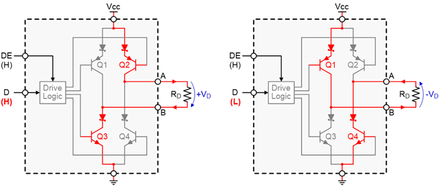
    There are diodes in the path from VCC to A/B as well as A/B to GND - but they aren't ESD diodes. Basically RS-485/RS-422 standard architecture includes diodes:

    But they wouldn't be considered standard ESD diodes or an ESD cell. 

    This device does have limited ESD protection - but not a typical ESD diode on A or B. 

    Best,

    Parker Dodson

  • Thank you - that's what it sounded like, but just wanted to make sure.

    Now a follow-on question: would there be any harm functionality-wise in adding external ESD diodes to VCC/GND?

  • Hi Stephen,

    So if you are talking about ESD protection on VCC to GND - I really don't see much concern in that at all as long as the diodes are shunting current during normal operation (i.e. loading the power supply).

    If you are talking about adding ESD protection from A/B to VCC/GND - it depends on when the diodes start conducting and how much capacitance they have. While protection diodes aren't uncommon on A and B to GND (usually nothing is attached to VCC from A or B except maybe a biasing resistor )  usually they are less for ESD and more for transients and/or surges and have a bi-directional working voltage of 12V and -7V (so not to reduce common mode range). High capacitance from the diodes can also work to reduce effective bus length - but this is usually more of a niche issue where reduction of common mode range is the main concern.  Under normal operating conditions with no ground potential shifts between communications nodes 5V diodes wouldn't conduct as the single ended voltage on either line will be less than VCC (by at least 1 diode drop) - so depending on exact use case you may not need as robust of a diode - but in general the main concern is to ensure they aren't cutting into your common mode range and if the system is very long (which is relative to frequency/data-rate) then the capacitance of the diodes could negatively impact performance.

    Please let me know if that cleared up your question - of if I misunderstood anything please let me know. As always if you have additional questions please don't hesitate to ask!

    Best,

    Parker Dodson

  • Hello Parker,

     Sorry for being a little less than descriptive. I'm looking at the case when the standard bidirectional TVS protection (+12V/-7V) isn't enough for surge events (like lightning) because, for instance, their positive clamping voltage approaches 23V - which is enough to exceed the max ratings on the bus pins.  So perhaps I should start there, rather than suggesting a possible circuit solution: I assume the input +15V/-10V max rating of the DS16F95QML is with respect to the GND pin.  If that is true, how can the bus pins be protected from a surge event that pushes the applied voltages close to the TVS clamping voltages?

    Steve

  • Hi Steve,

    So yes the 15V/-10V is w.r.t. ground - and if the pins experience over voltages we no longer guarantee it won't be damaged. So realistically the max clamping voltage should be between 15V and -10V to mitigate risk. 

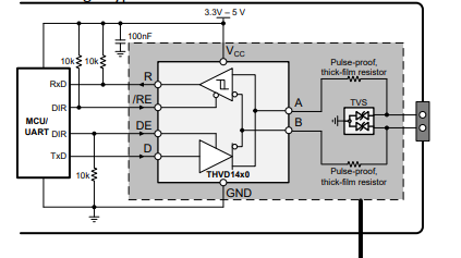
    Generally speaking - we suggest using pulse proof 10 Ohm resistors (thick film or wire wound)  at the I/O pins of RS-485/RS-422 devices

    (please disregard THVD14x0 on bottom of diagram - it applies to any RS-4xx device) 

    While this doesn't completely get rid of the clamping too high issue - it does help filter off some of the initial surge to help protect the device. Its not the best - generally speaking I usually will see fuses go along with the design to break if current is too high for the application. 

    But ultimately if you overvolt the bus pins damage isn't uncommon - and usually a robust external network would be needed - the above diagram is based off of a design that is for 500W surges. It is important to note - that whatever protection diode you are using make sure that you are looking at the max voltage for your application - as I do know there are diodes that are used that clamp higher than they should - but at an unrealistic current for the application. Generally speaking - higher power surge - more robust (expensive) diodes are needed. 

    Please let me know if you have any other questions!

    Best,

    Parker Dodson