This thread has been locked.

If you have a related question, please click the "Ask a related question" button in the top right corner. The newly created question will be automatically linked to this question.

DS90UB933-Q1: Signal integrity ssimulation

Part Number: DS90UB933-Q1

Hi,

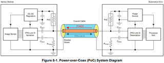
In the attached FPD Link-III spec, what is meant by PoC? Does it include the parasitics of the filter components (inductors,bead) as well?

Thanks,

Nandini

  • Hello Nandini,

    The document you posted a screenshot of is marked as NDA, so I edited your post. Please be careful when posting confidential or NDA material to the public E2E forum.

  • For your question, any component that touches the high-speed channel (from the serializer to the deserializer) will affect the Insertion Loss and Return Loss across the channel. In terms of PoC, this refers to the Power-Over-Coax circuit that is typically used in ADAS and COAX applications. The circuit allows the user to design a system where a power source is applied to the deserializer side of the board and power is sent to the serializer board, over the same cable that is transmitting high-speed video data. This architecture is typically implemented in systems to save on cost and reduce space.

    We have some short learning videos on this PoC topic:

    https://www.ti.com/video/series/fpd-link-learning-center.html

    Our ADAS datasheets also typically have a diagram of PoC.

    The PoC circuit is used to filter-out the DC signal from the AC signal, so that DC power and AC high-speed signals can be sent on the same COAX cable, with no issue. The PoC network adds some Insertion Loss on the overall high-speed channel, since the inductors/ferrite beads used in the network are not ideal and can't perfectly isolate the DC signal from the AC signal over the entire wide-band frequency range that our devices operate at. There also may be Return Loss added to the designed channel, since adding components that touch the high-speed trace may cause some impedance mismatch in the system, which may cause reflections. 

    The IL/RL requirements we have defined in the Channel Specs document describe the required IL/RL that must be met across the entire channel, in order for our serializer and deserializer to be able to link and transfer video data, with no issues. The IL/RL limits defined in the document account for the added IL/RL when a PoC network is implemented in a system, so you need to make sure that the system that you develop meets the Total Channel Requirements (across all automotive temperature conditions and across all current loads in the active system).

    Also note that in the document, we recommend IL/RL budgets for the serializer and deserializer PCB and the cable, but only the Total Channel Requirement must be met across all worst-case operating conditions. That means you could implement a system with a lossier cable if you make-up for it in the PCB portion of the system, so long as you meet the Total Channel Requirements. And vice versa.

    Best,

    Justin Phan 

  • Thank you Justin for the details. I will take care of future queries.