Hi expert,
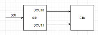
I previously used DOUT0 and DOUT1 to connect 948.
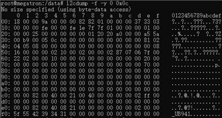
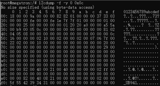
The following is the register configuration.
ds941_write_reg(0x03, 0x08); //Pass-Through Enabled
ds941_write_reg(0x01, 0x08); //Disable dsi input
ds941_write_reg(0x07, 0x82); //Slave id
ds941_write_reg(0x08, 0x82); //Slave Alias
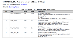
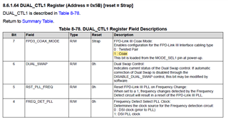
ds941_write_reg(0x5e, 0x7f); //Freq detect high threshold
ds941_write_reg(0x40, 0x04); //TSKIP_CNT programming
ds941_write_reg(0x41, 0x05); //TSKIP_CNT programming
ds941_write_reg(0x42, 0x09); //TSKIP_CNT programming
ds941_write_reg(0xc6, 0x21); //ISR
ds941_write_reg(0x0d, 0x07); //GPIO0
ds941_write_reg(0x0e, 0x33); //GPIO1 and GPIO2
ds941_write_reg(0x0f, 0x03); //GPIO3
ds941_write_reg(0x01, 0x00); //Enable dsi input
ds941_write_reg(0x03, 0x08); //ensure Pass-Through Enabled
Now I need to use only DOUT0 to connect 948
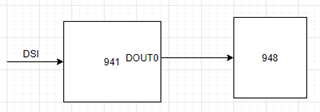
but failed with the original register configuration.
ds941_write_reg(0x03, 0x08); //Pass-Through Enabled
ds941_write_reg(0x01, 0x08); //Disable dsi input
ds941_write_reg(0x07, 0x82); //Slave id
ds941_write_reg(0x08, 0x82); //Slave Alias
ds941_write_reg(0x5e, 0x7f); //Freq detect high threshold
ds941_write_reg(0x40, 0x04); //TSKIP_CNT programming
ds941_write_reg(0x41, 0x05); //TSKIP_CNT programming
ds941_write_reg(0x42, 0x09); //TSKIP_CNT programming
ds941_write_reg(0xc6, 0x21); //ISR
ds941_write_reg(0x0d, 0x07); //GPIO0
ds941_write_reg(0x0e, 0x33); //GPIO1 and GPIO2
ds941_write_reg(0x0f, 0x03); //GPIO3
ds941_write_reg(0x01, 0x00); //Enable dsi input
ds941_write_reg(0x03, 0x08); //ensure Pass-Through Enabled
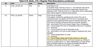
How do I modify the register configuration?
Thank you.