This thread has been locked.

If you have a related question, please click the "Ask a related question" button in the top right corner. The newly created question will be automatically linked to this question.

DS90UB954-Q1: MAP tool failure rate

Part Number: DS90UB954-Q1

Hi Team,

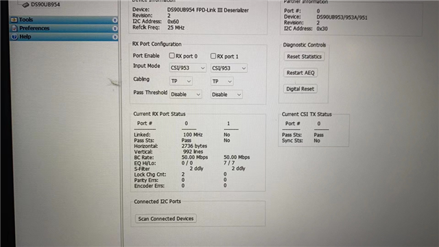
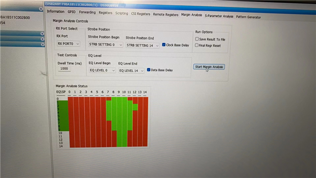
Customer use MAP tool to verify the link signal integrity and result showed below. There are two questions below:

  1. They test serval times and only first time failed, others are pass. Does this influence? Is there possibility the MAP tool bug cause first fail?
  2. Does MAP tool pass mean signal chain integrity are OK to use? If customer still found image error, any more methods or register need to be checked to debug?

Thank you!

Marc

Marc

  • Hi Marc,

    They test serval times and only first time failed, others are pass. Does this influence? Is there possibility the MAP tool bug cause first fail?

    If the results are similar across several tests, the first test result could have been impacted by the hardware or software setup. 

    Does MAP tool pass mean signal chain integrity are OK to use? If customer still found image error, any more methods or register need to be checked to debug?

    MAP tool passing specifically denotes passing link margin between the serializer and the deserializer. The link margin may be impacted by several characteristics such as PoC noise, and Channel specification limits. Margin Analysis Program runs by monitoring register 0x4D and 0x4E on the deserializer. 

    If an image error is detected, additional status registers can be read for debugging. These registers include CSI-2 status registers on the serializer and deserializer. An example of registers on the deserializer includes 0x55, 0x56, 0x7A, 0x7B. Serializer registers include 0x49, 0x52, and 0x5D-0x60.

    Best,

    Zoe 

  • Hi Zoe,

    Thanks for the reply. The I2C initialization code showed below and could you help review it?

    One thing I noticed is 0x60,W,0xD5,0x40, which means AEQ_MAX is Level 4 only, do you think if that's acceptable or any suggested value? Will this change influence other registers to change accordingly?

    0x60,R,0xF0,0x5F
    0x60,R,0xF1,0x55
    0x60,R,0xF2,0x42
    0x60,R,0xF3,0x39
    0x60,R,0xF4,0x35
    0x60,R,0xF5,0x34
    0x60,R,0xF0,0x5F
    0x60,R,0xF1,0x55
    0x60,R,0xF2,0x42
    0x60,R,0xF3,0x39
    0x60,R,0xF4,0x35
    0x60,R,0xF5,0x34
    0x60,R,0xBC,0x80
    0x60,R,0x01,0x00
    0x60,W,0x01,0x02
    0x60,R,0x00,0x60
    0x60,W,0x10,0x13
    0x60,R,0x03,0x20
    0x60,W,0x4C,0x01
    0x60,W,0x6D,0x7C
    0x60,W,0x58,0x5E
    0x60,W,0xBA,0x83
    0x60,W,0x1F,0x02
    0x60,R,0x0C,0x83
    0x60,W,0x0C,0xBF
    0x60,W,0xD5,0x40
    0x60,W,0xD4,0x70
    0x60,W,0x41,0xA9
    0x60,W,0x42,0x01
    0x60,W,0x43,0x03
    0x60,W,0xD2,0x8C
    0x60,R,0x4D,0x13
    0x60,R,0x4D,0x03
    0x60,W,0x72,0x00
    0x60,R,0x4D,0x03
    0x60,R,0x5B,0x30
    0x60,W,0x5C,0x12
    0x60,R,0x4D,0x13
    0x60,R,0x4D,0x03
    0x60,W,0x5D,0x6C
    0x60,W,0x65,0x14
    0x60,W,0x65,0x00
    0x60,W,0x4C,0x01
    0x60,W,0x5D,0x20
    0x60,W,0x65,0x10
    0x60,W,0x4C,0x01
    0x60,W,0x5D,0x10
    0x60,W,0x65,0x10

    0x60,R,0x20,0x30
    0x60,W,0x20,0x20
    0x60,R,0x32,0x00
    0x60,W,0x32,0x01
    0x60,W,0x33,0x03
    0x60,W,0x34,0x48
    0x60,W,0x4C,0x01
    0x60,W,0x7D,0x3C
    0x60,W,0xD5,0x40
    0x60,W,0xD4,0x70
    0x60,W,0x41,0xA9
    0x60,W,0x42,0x01
    0x60,W,0x43,0x03
    0x60,W,0xD2,0x8C
    0x60,R,0x4D,0x13
    0x60,R,0x4D,0x03
    0x60,R,0x03,0x20

    Thank you!

    Marc

  • Hi Marc, 

    Reviewing the write transactions provided, register 0x32 is written to a value of 0x1. This register is reserved in the DS90UB954 datasheet therefor I recommend this transaction is removed. 

    Secondly, in the AEQ configuration register 0x42 is written to 0x1, disabling FPD3 error checking. However, the subsequent transaction increases the AEQ error threshold. Would you be able to verify if FPD3 error checking during AEQ is desired in the system? The AEQ settings currently will consider the link to be ok if lock is available, regardless if there are parity or FPD3 clocking errors present. 

    The AEQ range is set to be 0-4 in this initialization script. Depending on the system configuration this may not be ideal. For instance, if there are varying cable lengths used in the system the ideal EQ value may differ. A wider range would enable adaptability in the system over time. Based on the results provided for MAP, the range is likely ok for the systems preference. The reduced range can enable faster lock time. 

    Let me know if there any additional questions!

    Best,

    Zoe