A related question is a question created from another question. When the related question is created, it will be automatically linked to the original question.
If you have a related question, please click the "Ask a related question" button in the top right corner. The newly created question will be automatically linked to this question.
DOUT is a standard inverted push-pull output driver connected to V+ and V-. There is an output resistance between driver output and bus. It can handle loads down to 3K ohms. Essentially from a design point of view this pin is either a low impedance to V- or a low impedance connection to V+ since it is always active. It should largely only be connected to a RS-232 RIN input so not to overload the bus although protection diodes are sometimes used. This is largely how we'd model this device if we put into a spice model as that is what matters in the vast majority of cases at a system level.
DIN is just a high impedance digital input that controls DOUT. Its high impedance and it has some leakage/input current that is up to +/-200uA - so as long as the controller can handle uA level current you should be fine here. If this were modeled we'd just put a leakage current source here to model the small input current.
ROUT is a standard inverted push-pull output as well - but the driver is connected to VCC and GND instead of V+ and V- . This is very similar in concept to DOUT drivers but less robust because the voltage level protection required is much lower on console side for RS-232.
RIN can just be thought of as a a 5K resistance to ground - as shown in the schematic. Its technically a high impedance input with an integrated pull-down - but since the pull-down is much stronger than the impedance of the actual receiver it acts as if it is just a 5K ohm load to ground on this pin.
All of these pins also have ESD diodes except RIN:
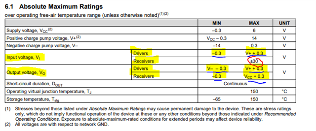
DOUT - ESD diodes from DOUT to V+ and another ESD diode from DOUT to V-; the diodes start to conduct at V+ + 0.3V or V- - 0.3V.
DIN - ESD diodes from DIN to VCC and another ESD diode from DIN to GND; diodes start conducting at -0.3V input and VCC + 0.3V (datasheet says V+ here - but the console pins aren't guided by charge pump voltages so this is a typo).
ROUT - ESD diodes from ROUT to VCC and another from ROUT to VCC - same as DIN.
RIN does not have standard ESD diodes
You can tell by looking at the abs max ratings - if the abs max rating is absolute (i.e. a number - unless the number is -0.3V or -0.5V then there is a diode from input to GND) then there is no standard ESD diode and if the number is an expression it has an ESD diode.
Highlights are points of interest
Blue underlines indicate ESD diode (Expression or -0.3V as -0.3V is just short form of GND - 0.3V since GND = 0V)
Red circle highlights no standard ESD cell on input voltage on Receivers - which is the RIN pin.
Generally speaking - the communication pins on RS-232 should be seen as more of a black box as described above as its system impacts are in the vast majority of cases explained by those approximations above. Also we can't share much more because the minor differences in how the transceiver works is something I can't really share since that is more protected and generally unnecessary information that won't generally improve a system level design. Under normal conditions the ESD diodes won't be conducting and can be ignored.
Please let me know if there are any other questions.