This thread has been locked.

If you have a related question, please click the "Ask a related question" button in the top right corner. The newly created question will be automatically linked to this question.

Unable to fetch the data through PEAK System P-CAN Trace Data logger for the CAN IC part number (SN65HVD230QDRG4Q1)


Dear Team,

Greetings in advance!

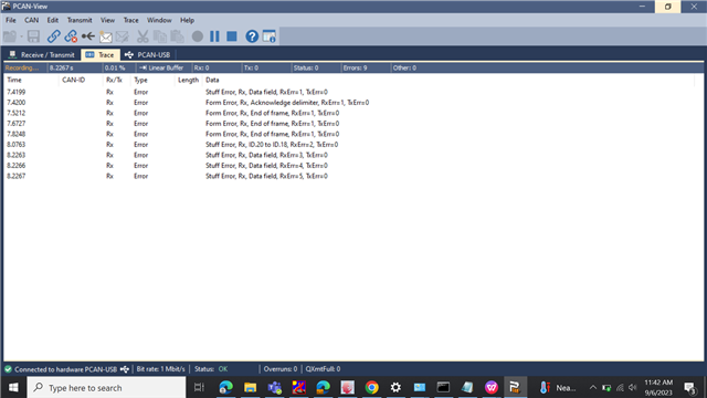
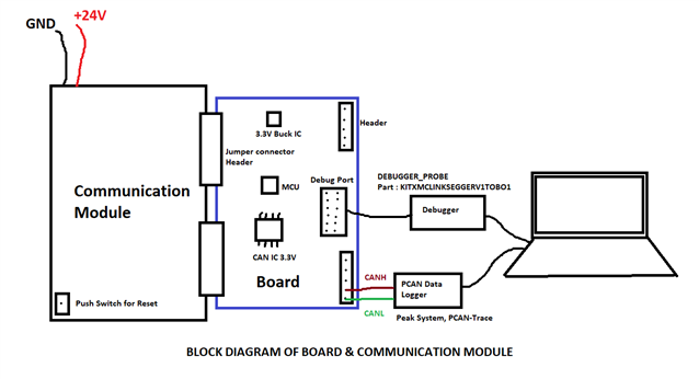
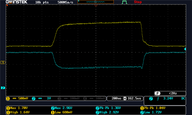
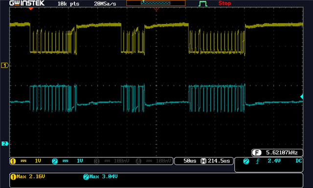
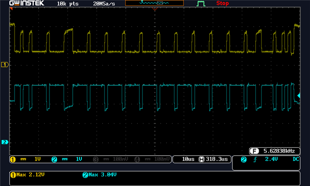
We have made a CAN circuit with CAN IC part number (SN65HVD230QDRG4Q1) & Controller we are using MCU Part number : XMC4108Q48K64BAXUMA1, But we are trying to fetch the data through PEAK System P-CAN Trace Data logger but we are unable to fetch the data, It showing some errors instead of showing Tx & Rx data. Some times it is unable to show anything. I have attached the error list for your reference. Note: We have Qty: 05 Nos. Identical PCB boards out of 05 board only one board is working fine but other boards are unable to fetch the data, We are keeping same (Same Firmware, already Checked other boards components including resistors & capacitors that are found OK, same setting for PEAK System P-CAN Trace Data logger). So, Team you are requested to suggest for any solutions for the same.


  • Arun,

    As we do not produce the PCAN-USB product, we are not experts on the software of the UI, but we can try and investigate what might be going on with your CAN system.

    I am imagining that there might be a physical layer issue that is preventing communication on the bus, generally due to reduced signal quality. Could you help include some additional analog information for us? Any or all of the following would help:

    • Oscilloscope plots showing the wave shape on your bus, ideally at both ends of the network.
    • An overview of your physical layer, including termination, capacitance, protection, etc.
    • Communication speed programmed for the network.
    • Sample point setting for your controllers.

    Additionally, I see you're using the SN65HVD230-Q1. Are all of the nodes on your network using 3.3 V CAN, or are you mixing a 5 V CAN network with a 3.3 V CAN network?

    Best,

    Danny

  • Hi Danny,

    First of all, I like to thank you for your valuable response.

    1. We are not mixing 5V CAN network to 3.3V
    2. We have connected our Board with Communication module
    3. We have given Communication speed according to our requirements
    4. Also for Sample point we have given according to our MCU

    5. All Boards are Factory made Identical PCBA Boards

    6. We have tested with Separate Split Termination for CAN IC also.

    We have tested & tried every possible combinations, Still we are unable to resolve this issue.

    I have attached some snaps for making your better understanding. 

  • Arun,

    Thank you for this additional information. Given that each of the nodes have identical hardware and software, my concern is that there is a hardware reliability issue with something on the physical layer. Generally, we can help diagnose this by taking a look at some oscilloscope plots to see if there is waveform distortion that would indicate what is causing the communication failure.

    From my understanding of the P-CAN system, a BUSHEAVY error corresponds to an error-passive condition, where the error node has stopped attempting to interject with an error frame. If there are only two devices on the bus, as is the case here, then no node would acknowledge the transmitted frame and it would continue to attempt to retransmit its data. During this time, the receiving node would remain in the error-passive state.

    Would it be possible to obtain some probed images of CANH/CANL on an oscilloscope trace? This might help diagnose what is going on with this network.

    Best,

    Danny

  • Hi Danny,

    Thank you again for your valuable reply,

    Some Experiments we did yesterday added with 120E terminal resistance that some glimpse I have shared with you with Oscilloscope for making your more better clear understanding.

    I have one question for you that any kind of ESD (Electro Static Discharge) may effect our non working boards specially MCU & CAN IC?

    Can I try with replacing the MCU & CAN IC (if IC's are really effected) will it be a solutions?

    Working boards CAN logs data are coming proper into Oscilloscope (as per attachments).

    Note : Some glimpse of pictures (including working Boards & Non working boards Osc. images) & Block diagram of our Experiments are added for your reference.

  • Arun,

    Danny is out of office until next week. We will have a response to you by Wednesday. Thank you for your patience.

    Regards,

    Eric Hackett 

  • Arun,

    Apologies for the delay while I was out of office the past few business days.

    Interesting, I don't particularly see what might be causing these errors since I don't see an error frame on the bus somewhere (six or more consecutive dominant bits). Is your first image a plot of the bus when it is not operating? If so, it seems clear that neither device is attempting to transmit data, which could mean one of them has gone into bus-off state.

    Yes, ESD can definitely cause damage to the device or to the MCU, however if the MCU is capable of handling communication at all, I find it unlikely that the MCU would have sustained damage that causes this. It would be much more likely for the transceiver itself to sustain damage that would prevent communication. Are any of the plots above images of the faulty board attempting to transmit a frame? If we see abnormal waveform shape in those images, it would be an indication of some sort of damage to the driver.

    Also, you mention 120 Ω termination above. Am I correct that you mean 120 Ω in parallel with another 120 Ω termination elsewhere to produce a total of 60 Ω termination for the bus? The transceivers expect a total of ~60 Ω for the network.

    Best,

    Danny