This thread has been locked.

If you have a related question, please click the "Ask a related question" button in the top right corner. The newly created question will be automatically linked to this question.

DP83822I: Network speed issue

Part Number: DP83822I

Hi Team,

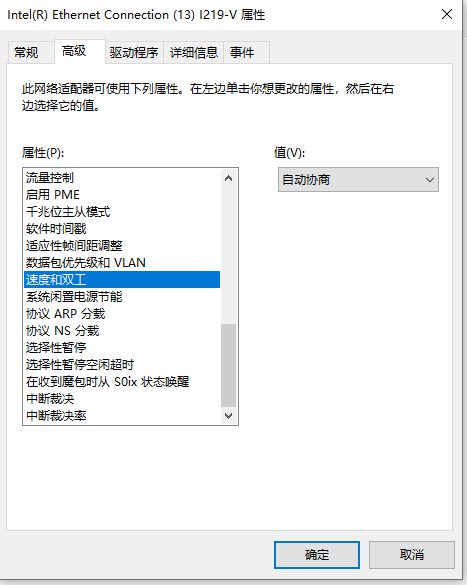
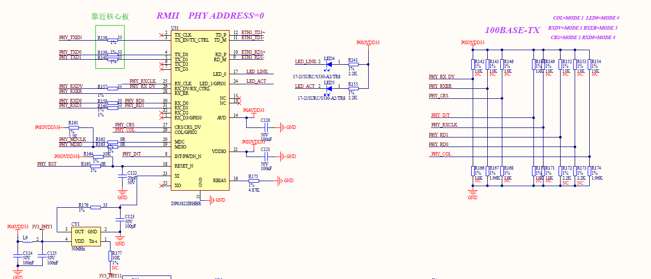
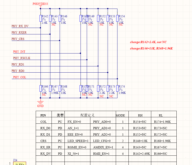
RMII communication mode of DP83822I phy chip is being used on ARM A7. After debugging, it was found that the service side could only be pinged through 10Mbps/full. The customer tried to force to set 100Mbps/full rate but failed. The service side on customer end is 100 Mbps/full which will result in a large number of packet loss. The following are the current communication conditions and the register data: 

root@:~# fec 2188000.ethernet eth0: Link is Down

root@:~# fec 2188000.ethernet eth0: Link is Up - 100Mbps/Full - flow control rx/tx
fec 2188000.ethernet eth0: Link is Down
fec 2188000.ethernet eth0: Link is Up - 100Mbps/Full - flow control rx/tx
fec 2188000.ethernet eth0: Link is Down
fec 2188000.ethernet eth0: Link is Up - 100Mbps/Full - flow control rx/tx
fec 2188000.ethernet eth0: Link is Down
fec 2188000.ethernet eth0: Link is Up - 100Mbps/Full - flow control rx/tx
fec 2188000.ethernet eth0: Link is Down
fec 2188000.ethernet eth0: Link is Up - 10Mbps/Full - flow control rx/tx

root@:~# ping 192.168.1.100
PING 192.168.1.100 (192.168.1.100) 56(84) bytes of data.
64 bytes from 192.168.1.100: icmp_seq=1 ttl=200 time=1.85 ms
64 bytes from 192.168.1.100: icmp_seq=2 ttl=200 time=0.909 ms
64 bytes from 192.168.1.100: icmp_seq=3 ttl=200 time=1.25 ms
64 bytes from 192.168.1.100: icmp_seq=4 ttl=200 time=1.01 ms
64 bytes from 192.168.1.100: icmp_seq=5 ttl=200 time=1.09 ms
64 bytes from 192.168.1.100: icmp_seq=6 ttl=200 time=1.04 ms
64 bytes from 192.168.1.100: icmp_seq=7 ttl=200 time=1.05 ms
64 bytes from 192.168.1.100: icmp_seq=8 ttl=200 time=1.22 ms
64 bytes from 192.168.1.100: icmp_seq=9 ttl=200 time=1.18 ms
64 bytes from 192.168.1.100: icmp_seq=10 ttl=200 time=1.24 ms
64 bytes from 192.168.1.100: icmp_seq=11 ttl=200 time=1.02 ms
64 bytes from 192.168.1.100: icmp_seq=12 ttl=200 time=0.970 ms
64 bytes from 192.168.1.100: icmp_seq=13 ttl=200 time=1.15 ms
64 bytes from 192.168.1.100: icmp_seq=14 ttl=200 time=1.02 ms
64 bytes from 192.168.1.100: icmp_seq=15 ttl=200 time=0.923 ms
64 bytes from 192.168.1.100: icmp_seq=16 ttl=200 time=1.17 ms
64 bytes from 192.168.1.100: icmp_seq=17 ttl=200 time=1.07 ms
64 bytes from 192.168.1.100: icmp_seq=18 ttl=200 time=1.08 ms
64 bytes from 192.168.1.100: icmp_seq=19 ttl=200 time=1.12 ms
64 bytes from 192.168.1.100: icmp_seq=21 ttl=200 time=1.10 ms
64 bytes from 192.168.1.100: icmp_seq=22 ttl=200 time=0.871 ms
64 bytes from 192.168.1.100: icmp_seq=24 ttl=200 time=1.18 ms
^C
--- 192.168.1.100 ping statistics ---
24 packets transmitted, 22 received, 8% packet loss, time 23042ms
rtt min/avg/max/mdev = 0.871/1.116/1.850/0.195 ms
root@:~#

phy addr          value

0x0000             0x3100

0x0001             0x786d

0x0002             0x2000

0x0003             0xa240

0x0004             0x5e1

0x0005             0xcc61

0x0006             0xf

0x0007             0x2001

0x0008             0x4006

0x0009             0x0

0x000a             0x100

0x000b             0x1000    

0x000f             0x0

0x0010             0x1817

0x0011             0x108

0x0012             0xf600

0x0013             0x2200       

0x0016             0x100

0x0017             0xa1

0x0018             0x400

0x0019             0x3000         

Could you help look into this case? Thanks.

Best Regards,

Cherry

  • Hi Cherry,

    From the logs, I see that the link partner side is not advertising 100M at all. This can be seen from register 0x0005. Can you please check why this is the case?

    --
    Regards,
    Gokul.

  • Hi Gokul,

    Thank you for the support.

    The customer uses the same net wire to test the other net port (eth1) on their PCB. When the network cable is plugged in, 100baseTx-FD is negotiated automatically and the link partner is good. However, link partner does not display properly when plugged into eth0 (DP83822):

    root@imx6ul7d:~# mii-tool -v
    eth0: negotiated 10baseT-FD flow-control, link ok
    product info: vendor 08:00:28, model 36 rev 0
    basic mode: collision test, autonegotiation enabled
    basic status: autonegotiation complete, link ok
    capabilities: 100baseTx-FD 100baseTx-HD 10baseT-FD 10baseT-HD
    advertising: 100baseTx-FD 100baseTx-HD 10baseT-FD 10baseT-HD flow-control
    link partner: 10baseT-FD 10baseT-HD flow-control
    eth1: no link
    product info: vendor 00:07:32, model 8 rev 2
    basic mode: autonegotiation enabled
    basic status: no link
    capabilities: 100baseTx-FD 100baseTx-HD 10baseT-FD 10baseT-HD
    advertising: 100baseTx-FD 100baseTx-HD 10baseT-FD 10baseT-HD flow-control
    SIOCGMIIPHY on 'eth2' failed: Operation not supported
    root@imx6ul7d:~# fec 2188000.ethernet eth0: Link is Down
    
    root@imx6ul7d:~#
    root@imx6ul7d:~# ifconfig eth1 up
    IPv6: ADDRCONF(NETDEV_UP): eth1: link is not ready
    root@imx6ul7d:~# ifconfig eth1 upIPv6: ADDRCONF(NETDEV_CHANGE): eth1: link becomes ready
    
    root@imx6ul7d:~# ifconfig eth1 up
    root@imx6ul7d:~# ifconfig eth1 192.168.2.137
    root@imx6ul7d:~#
    root@imx6ul7d:~# ping 192.168.2.100
    PING 192.168.2.100 (192.168.2.100) 56(84) bytes of data.
    64 bytes from 192.168.2.100: icmp_seq=1 ttl=200 time=2.45 ms
    ^C
    --- 192.168.2.100 ping statistics ---
    1 packets transmitted, 1 received, 0% packet loss, time 0ms
    rtt min/avg/max/mdev = 2.452/2.452/2.452/0.000 ms
    root@imx6ul7d:~#
    root@imx6ul7d:~#
    root@imx6ul7d:~# mii-tool -v
    eth0: no link
    product info: vendor 08:00:28, model 36 rev 0
    basic mode: collision test, autonegotiation enabled
    basic status: no link
    capabilities: 100baseTx-FD 100baseTx-HD 10baseT-FD 10baseT-HD
    advertising: 100baseTx-FD 100baseTx-HD 10baseT-FD 10baseT-HD flow-control
    eth1: negotiated 100baseTx-FD flow-control, link ok
    product info: vendor 00:07:32, model 8 rev 2
    basic mode: autonegotiation enabled
    basic status: autonegotiation complete, link ok
    capabilities: 100baseTx-FD 100baseTx-HD 10baseT-FD 10baseT-HD
    advertising: 100baseTx-FD 100baseTx-HD 10baseT-FD 10baseT-HD flow-control
    link partner: 100baseTx-FD 100baseTx-HD 10baseT-FD 10baseT-HD flow-control
    root@imx6ul7d:~#

    Thanks and regards,

    Cherry

  • Hello Cherry,

    What is the link partner used? It would be better for me to understand if you can share a block diagram of the setup.

    Regarding the above log you shared above, is it captured on the host connected to DP83822?

    --
    Regards,
    Gokul.

  • Hi Gokul,

    What is the link partner used?

    PC is being used.

    is it captured on the host connected to DP83822?

    Yes.

    Thanks and regards,

    Cherry

  • Hello Cherry,

    Is the eth1 (other port of PCB) DP83822 or some other PHY?

    Can you please ask customer to test connecting eth1 port to eth0 and see if the device is linking up in 100M-FD mode?
    Please share the logs of 0x00 to 0x1F, 0x0467, 0x0468 registers during this experiment.

    --
    Regards,
    Gokul.

  • Hello Gokul,

    Is the eth1 (other port of PCB) DP83822 or some other PHY?

    It's some other PHY, not DP83822.

    The ETH0 uses DP83822 and the register logs are as follows: 

    0x00              0x3100

    0x1F              0x0

    0x0467          0x2001

    0x0468          0x4006

    Thanks and regards,

    Cherry

  • Hello Cherry,

    Can you please ask customer to test connecting eth1 port to eth0 and see if the device is linking up in 100M-FD mode?

    Can you please ask customer to check the link and speed after connecting eth1 to eth0, instead of connecting to a PC.

    Please share the logs of 0x00 to 0x1F, 0x0467, 0x0468 registers during this experiment.

    Please share the logs (during the above experiment) of registers 0x00 to 0x1F (all registers from 0x00 to 0x1F, not just 0x00 and 0x1F) and 0x467, 0x468.

    Can you please share the schematic of the board?

    --
    Regards,
    Gokul.

  • Hi Gokul,

    Can you please ask customer to check the link and speed after connecting eth1 to eth0, instead of connecting to a PC.

    They've tried to connect eth1 to eth0 but it failed for unknown reason.

    Please see the schematic here:

    Thanks and regards,

    Cherry

  • Hi Cherry,

    Here are my comments on the schematic.

    1. The strapping doesn't look as expected. From the schematic, customer want to use RMII mode with PHY Address 0.
      But RX_DV is not set into Mode 3.
      The description of modes of straps in the schematic doesn't match the requirement and what is implemented in the schematic.
    2. LED_1 should not be active low LED, unless it is strapped to Mode4. I see from the logs, LED_1 is strapped into a mode which should not be used.
      I suggest depopulating connections on LED_1
    3. Please check if the PHY needs to be in RMII mode or RMII_50 mode and configure straps accordingly.

    --
    Regards,
    Gokul.

  • Hi Gokul,

    For comments #1 and #3, the customer have determined that the PHY requires RMII_50 mode and that RX_DV has been configured for mode 4 (the modifications are not made in the schematic). 

    For comment #2, they don't have a need for an LED so it can be ignored for now.

    Thanks and regards,

    Cherry

  • Hi Cherry,

    From the logs, the strapping is somehow not going through properly.

    Can you please recapture the logs of 0x00 to 0x1F and 0x0467 and 0x468 registers after depopulating LED4 and LED5 components on the board?

    --
    Regards,
    Gokul.

  • Hi Gokul,

    Can you please recapture the logs of 0x00 to 0x1F and 0x0467 and 0x468 registers after depopulating LED4 and LED5 components on the board?

    Please see here:

    phy addr          value

    0x0000             0x3100

    0x0001             0x786d

    0x0002             0x2000

    0x0003             0xa240

    0x0004             0x5e1

    0x0005             0xcc61

    0x0006             0xd

    0x0007             0x2001

    0x0008             0x4006

    0x0009             0x0

    0x000a             0x100

    0x000b             0x1000    

    0x000f             0x0

    0x0010             0x1817

    0x0011             0x108

    0x0012             0xf600

    0x0013             0x2200       

    0x0016             0x100

    0x0017             0xa1

    0x0018             0x400

    0x0019             0x300

    0x001a             0x10

    0x001b            0x7d

    0x001c            0x5ee

    0x001d            0x0

    0x001e            0x2

    0x001f             0x0

    0x0467            0x2001

    0x0468            0x4006

    Thanks and regards,

    Cherry

  • Hi Cherry,

    While you were sharing the logs of registers 0x0467, 0x0468, I noticed some errors which led to wrong conclusions on the strapping.

    Upon detailed look at the values of registers 0x0467 and 0x0468, I see that the values are a mirror of registers 0x0007 and 0x0008. This means that the extended register access is not used correctly.
    To read registers 0x0467 and 0x0468, can you please ask customer to following indirect access as outlined in section 8.4.2.1 of the datasheet?

    With all these, I feel that the strapping is fine except for CRS pin where the registers are not mounted appropriately. Please ask the customer to correct the pull up and pull down resistors on CRS pin. This wrong resistors on CRS pin should not affect the link-up, but the issue is somewhere else.

    From the logs, I still see that link partner is not advertising 100M full duplex. Please refer to register 0x5 description.
    To isolate whether it is a DP83822 issue or the Link Partner issue, can you please connect ETH0 and ETH1 ports and share the logs of 0x00 to 0x1F, 0x0467, 0x0468 registers?
    Otherwise, you can carry out the experiment with linking up two boards of DP83822. Sharing logs with this setup also works.

    --
    Regards,
    Gokul.

  • Hi Gokul,

    Customer tried to connect the two DP83822's eth ports with a network cable and found that they did not have a network connection after power up. That is, it only happens when connecting to your PC. 

    Thanks and regards,

    Cherry

  • Hi Cherry,

    I didn't quite get what it means that there is no network connection.

    We are not looking for ping, but to understand whether the link is up or not. When connecting two DP83822, do we see link-up? Can you please share the logs of registers 0x00 to 0x1F, 0x0467. 0x0468, like I requested earlier?

    --
    Regards,
    Gokul.

  • Hi Gokul,

    When connecting two DP83822, do we see link-up?

    No.

    Can you please share the logs of registers 0x00 to 0x1F, 0x0467. 0x0468, like I requested earlier?

    Since there is no link-up, the logs of register 0x00 to 0x1F, 0x0467, 0x0468 are same as the logs shared above.

    Thanks and regards,

    Cherry

  • Hi Cherry,

    In the logs above, we don't have the correct values of registers 0x0467 and 0x0468.

    In the logs for link between two DP83822, can you please confirm that the values of 0x0004 and 0x0005 are the same? I expect them to be different from the values in the above logs.

    Please share the values of 0x0004 and 0x0005 on both the DP83822 PHYs.

    --
    Regards,
    Gokul.

  • Hi Gokul,

    Please see the values that the end customer shared:

    phy addr          value

    0x0467             0x2001

    0x0468             0x5802

    0x0004             0x5e1

    0x0005             0xcde1

    Thanks and regards,

    Cherry

  • Hi,

    May I know is there any updates?

    Thanks and regards,

    Cherry

  • Hi Cherry,

    Apologies for the delay in response.

    My colleague who is an expert in Standard Ethernet will help you further on this issue.

    Sorry, again for the delay in response.

    Regards,
    Rahul

  • Hi Cherry,

    I see that this thread has gone silent so I will be taking over. There has been quite a bit of back and forth and I want to be sure that I'm understanding the setup and issue correctly. You are able to communicate in 10 Mbps but the goal is 100 Mbps, where you are currently seeing packet-loss.

    Generally in Debugs the first step would be what Gokul mentioned above:

    1. Read Registers 0x0467 & 0x0468. The purpose of doing this is to confirm that the PHY is in the correct Mode. 
      1. The following FAQ provides more details as to how these registers might be affected
        1. How to Confirm Ethernet PHY Strapping
      2. As Gokul mentioned before, both of these registers are Extended Registers and cannot be read directly.
        1. This FAQ provides more details on how to perform extended register reads
          1. Extended Registers
      3. Has the Schematic been updated to reflect the strap settings? Below is our schematic checklist that can be given to the customer
        1. The Pin-wise Checklist tab will help with pin connections
        2. The Straps Tool tab helps choose the correct strapping resistors to achieve the correct mode.
        3. Please note that Orange Boxes are drop down menus that can be selected
          1. https://e2e.ti.com/cfs-file/__key/communityserver-discussions-components-files/138/0243.DP83822_5F00_Schematic_5F00_Design_5F00_Review_5F00_Checklist.xlsb

    I apologize if it feels like you have already gone through these steps, but I want to be sure that PHY settings are correct. If the PHY is in the wrong mode, it'd be no wonder that it is misbehaving.

    Regards,

    Alvaro