This thread has been locked.

If you have a related question, please click the "Ask a related question" button in the top right corner. The newly created question will be automatically linked to this question.

TUSB212: Interface forum: TUSB212 control via I2C

Part Number: TUSB212
Other Parts Discussed in Thread: TUSB214,

Hello.

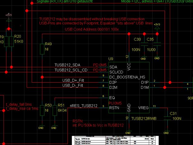
we want to control TUSB214 via I2C,

we have pullups on SDA/SCL, we can read/write register inside the device.

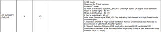
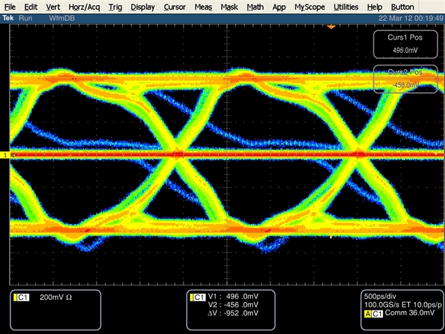
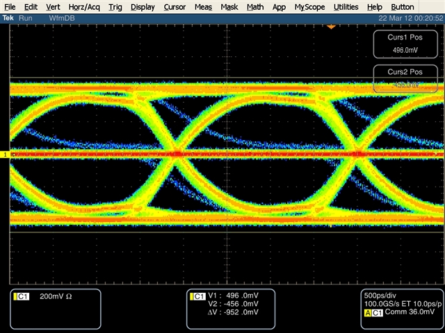
But whatever we try to set,  DC/AC boost in register 0x01, 0x0e, 

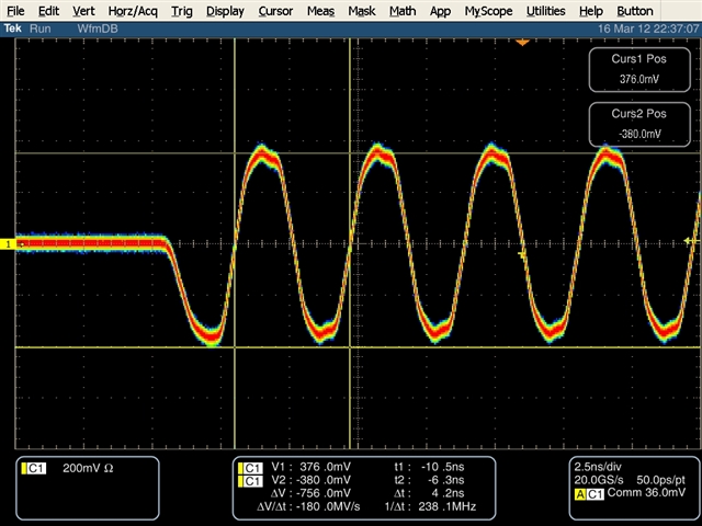
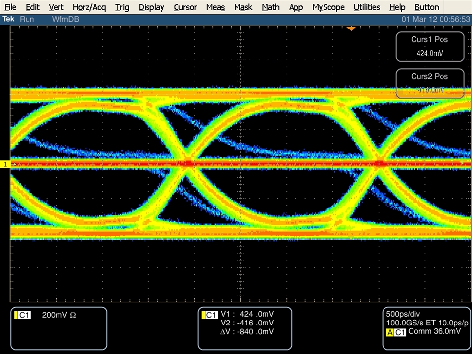
nothing changes the eye diagram or normal scope picture.

after reset we read default values:

=> i2c md 2c 1; i2c md 2c 3; i2c md 2c 0e
0001: 78
0003: 35
000e: 0d

then we set something else

=> i2c mw 2c 1 0; i2c mw 2c e 7;

read back

=> i2c md 2c 1 1; i2c md 2c e 1;
0001: 00
000e: 07

set from configuration mode to normal mode

i2c mw 2c 3 34; i2c md 2c 1 1; i2c md 2c e 1;
0001: 00 .
000e: 07 .

we don't see absolutely no changes on the signals.

we use compliance test pattern generator, included in processor NXP LS1046

it generates a packet which contains low speed, full speed, high speed pattern.

Thanks for any hints,

Best Regards,

Mike

  • Hi Mike,

    Before and after the device goes into configuration mode, what are the values of the CD and ENA_HS pin? Are they both high, indicating that the redriver is enabled? Or are they low?

    Additionally, if you have any eye diagrams you can send, that may be helpful for me to see if there are any indications of the eye changing.

    For schematic, it seems correct to me.

    Please let me know what comes back on the CD/ENA_HS pins., and if you have any other questions.

    Thanks,

    Ryan

  • Hello Ryan,

    thanks for help, and sorry for late reply,

    I measure CD = high, ENA_HS = low in all cases, 

    when device is in reset,

    when reg at 0x03 is 0x35, (configuration mode) or

    when reg at 0x03 is 0x34, (normal mode)

    CD should be high because it is SCL in I2C mode,

    we have nothing connected to ENA_HS, 

    How should it behave ?

    I tried test pattern from processor and usb stick to have more HS pattern in signal

    attached the eye diagram and diagram in normal mode, no changes if TUSB212 is in normal/configuration or reset.

    the signals look pretty strong, we matches the mask,

    but we want to understand why TUSB212 does absolutely nothing

    Best Regards,

    Mike


  • Hi Mike,

    If the TUSB212 is enabled, then both the CD and ENA_HS pins should be pulled high. As you noted, SCL is being used for I2C, so the best indicator would be the ENA_HS pin. The ENA_HS pins should pull high once any USB2 High Speed signal is detected by the device, either from the presence of HS TEST_PACKETS or a successful HS handshake as indicated below.

    The fact that this pin is not going high leads me to believe that the device does not believe it is seeing a high-speed signal.

    There are a few things I would like to test: Would it be possible to try using the redriver in pin-strap mode rather than I2C and seeing if that improves performance? Or if the CD and ENA_HS pins even change.

    Additionally, I would like to see what happens if you hold the redriver in RSTN while the enumeration/HS Handshake process is carried out, and then enable the redriver afterwards.

    Please let me know.

    Thanks,

    Ryan

  • Hello Ryan,

    1)

    I hold the device in reset, enable USB Test pattern Generator, release the reset:

    no changes at the signals, also  ENA_HS keeps low 

    2)

    I removed pullup from SCL/CD, removed signal from processor SCL, to let the device enter the non-I2C mode

    CD and ENA_HS are floating, after system power up ENA_HS goes immediately high,  CD stays low.

    I enable USB Test pattern Generator, CD goes immediately high, means according to datasheet, device has recognized a HS pattern.

    I can measure significant changes of signal, higher voltages, 

    I hold the device in reset, signals fall back like I measured before.

    Seems to me I2C mode doesn't really work ??

    Best Regards,

    Mike

    non I2C mode, CD/ENA_HS = high


    device is in reset

  • Hi Mike,

    Looking at these pictures, I would agree, seems that for some reason, I2C mode is either unable to leave configuration mode, or is inhibiting detection of the signal. Would it be possible for you to try writing and reading with I2C, this time also reading the value of 0x03 to ensure that bit 0 of the register is being set to 0 as it should be to come out of config mode into normal mode?

    I am working on getting a setup going in the lab here locally, and will let you know what I find with my own testing.

    Thanks,

    Ryan

  • Hello Rain,

    I can confirm that the bit 0 in reg: 0x03 is reset when I write a 0x34, I read back a 0x34.

    it is 0x35 after power up per default

    Regards,

    Michael

  • Hi Michael,

    Ok, got it, thanks for checking. Are you currently using the device on the board from the schematic you posted further up in this thread, or are you using an EVM?

    I am still working on replicating the results in the lab on our side, but should be able to provide you with results from our side by EoD tomorrow. Sorry about that.

    Thanks,

    Ryan

  • Hi Michael,

    I was able to get a setup going in the lab, and I can see the redriver enabling when using I2C. Here is the order for how I am testing this:

    RSTN Toggle > Check value of 0x03, which is 0x35 coming out of reset > Change values of 0x01 and 0x0E as wanted > Change value of 0x03 to 0x34 > Enable Test Packet

    After going in this order, I can see the redriver enabling on the scope, with the changes settings taking effect.

    Thanks,

    Ryan

  • Hello Ryan,

    Thank you for update,

    that is really odd, I tried exactly the same sequence several times and couldn't measure any signal changes.

    Can you please tell me which resistors do you have on SDA/SCL (I guess pullups) and on ENA_HS and EQ ?

    which values you wrote into reg 0x01 and 0x0e before setting 0x03 to 0x34

    I want to setup exactly the same on my board

    Regards,

    Michael

  • Hi Michael,

    For the SDA/SCL, our EVM does not have any pull-ups for those pins on the board. Instead, I used an AARDVARK I2C/SPI host adapter which has a 2.2KOhm resistor on each line to pull-up those pins and communicate.

    For ENA_HS and EQ, EQ was set to level 1 and BOOST was set to middle boost on the pin-strap. For 0x01 and 0x0e, I tried multiple settings, ensuring they properly changed. Each time, I would read the values of the register and change only the relevant bits, I.E if after reset ACB_LVL had a value of 0x18, I would change it from 0x18 to 0x78 for going from AC boost level 1 to level 3.

    For the pullups, keep in mind that TI recommends having 4.7KOhm resistors for pulling up SDA/SCL. The AARDVARKS 2.2KOhms also works.

    Also, just keep in mind that each time config mode is entered and then exited, it would be best to disable the test packets and turn them back on faster making the changes and exiting config mode.

    Please let me know!

    Thanks,

    Ryan