This thread has been locked.

If you have a related question, please click the "Ask a related question" button in the top right corner. The newly created question will be automatically linked to this question.

DP83620: signal values of PMD output pair signals slightly exceeding 1.05V

Part Number: DP83620

HI

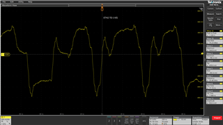
We are using DP83620SQE in our design along with AM625x. We are doing DVT analysis of our board and found the captures of the PMD output pair slightly exceeding 1.05V(max value as per datasheet). Please refer waveform below. It is 1.058V. We are using differential probe to validate these signals. Please let us know how much overshoot is allowable for these signals.
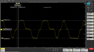
  • Hi Premalatha,

    I see from the image that the DC voltage is not cancelled. This might be caused by the probe or oscilloscope itself.

    When looking at peak-peak, the voltage is close 2V, which means that when DC voltage is cancelled, we can expect 1V as the measured value.
    On the top of output voltage, standard allows for a transient overshoot of 5% (i.e., 50mV).

    So, looking at the waveforms, the outputs look as expected and within the IEEE specifications.

    --
    Regards,
    Gokul.

  • HI Gokul,

     When we verified on couple of other boards there were times when this voltage went to 1.08V.Since we are marginally passing, is there a way to reduce this overshoot ?Pls let us know.

  • Hi Premalatha,

    Can you please let me know what is the value of overshoot measured with DC voltage removed?
    You can share the plots if you have them.

    When measured part-to-part, there will always be change in overshoot. We can't do much to reduce it if it is very low in the first place. Standard anyway allows +/-5% overshoot.

    --
    Regards,
    Gokul.

  • Hi Gokul

    We captured the differential signals using single ended probes in AC mode. Is this the way you had asked us to capture? pls let us know, as we are seeing pk-pk as 1.3V.

    We have used 1ghz probe(3.9pf).

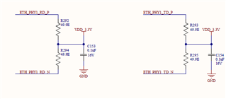
    On the same note, we want to understand if the marginal pass condition can be improved by any termination adjustment. Currently we have the below termination on TX and RX lines. which are placed closer to the ethernet phy IC. Pls let us know.

  • Hi Premalatha,

    Is the behavior observed in the above waveforms seen on multiple devices consistently?

    The waveforms are not supposed to look that way.
    My guess is either, there might be something wrong with the setup or PHY or board components got damaged.

    --
    Regards,
    Gokul.

  • Hi Gokul,

    We verified on 2 boards and its the same kind of waveforms we are getting.

    We want to understand why we should not measure differential signals using differential probe? Why we need to measure them w.r.t GND? PLs let us know.

    Also on the aspect of terminations, is there a necessity to fine tune them to reduce overshoot? pls advice.

  • Hello Premalatha,

    The image attached on 20th September seems to be as expected. What changed from then?

    The signal measured should be measured using a high impedance differential probe.

    --
    Regards,
    Gokul.

  • Hi Gokul

    We initially used differential probes.But after you had asked us to capture with DC cancelled , we used single ended probes. 

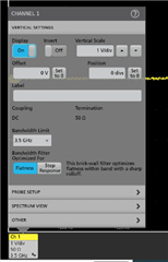
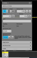
    With differential probe following are the settings, all these are default settings and we haven't changed anything.

    pls let us know if there are any concerns in the way signals are captured.

  • Gokul,

    Please recommend the proper way to measure these signals, what type of probe, bandwidth setting, AC/or DC coupled, placement of the probe when being measured...Etc..

    Is there an applications note on how to measure these signals available?

    Also, is there a possibility that this is being caused by trace mismatch or baseline wander?

    Shawn

  • Hi Premalatha,

    The signals should be measured with a high impedance differential probe. The setup you used initially is correct. I was just trying to eliminate any errors contributed by probe and scope.

    This is the setup required

    DP83620 -> 50ohm resistor network to 3.3V -> Magnetic -> RJ45 connector -> RJ45 cable less than 2 inch -> 100ohm load board
    On 100ohm load board, TD_P, TD_M signals should be terminated differentially with a 100ohm termination.
    The voltage should be probed across the 100ohm resistor using a high impedance differential probe.

    Before measuring, can you please verify if the probe gives 0V when disconnected from the PHY? This will probably give you the common mode voltage contributed from the probe and oscilloscope.

    Since a magnetic is used and the cable to be used is less than 2 inch, I don't think there will be a lot of baseline wander.

    --
    Regards,
    Gokul.

  • Gokul,

    Provided there is no conclusion or change in results from the above measurement, what other factors could contribute to this and cause the variance in results seen?

    EMI?

    Trace mismatch?

    Supply voltage variance?

    Shawn

  • Hi Gokul

    We are not using any specific test fixture to validate ethernet. We are connecting it to a host PC and verifying the signals.In that case , can we account for the minimal deviation we are seeing on these lines due to the parasitics of the test setup and conclude? Pls  let us know

    To answer your query regarding the probe, yes its gives 0V when disconnected from PHY.

  • Prema,

    1. What types of cables are being used for this measurement?
    2. If your change cables, do they see different results?
    3. Can you confirm your load via an impedance measurement?
    4. Are you seeing this same behavior on both PHY TX channels or only one of the PHYs? 
    5. Could you provide a scope shots of the VREF pins of both PHYs as well as the IO-VDD pins for these when this is occurring? 
    6. Finally, what does the VDD_3.3V_NW rail look like on the TS3L4892RHHR switch when this occurs?

    Shawn

  • Hi Shawn

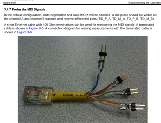
    We made a test setup using 100 ohms load on the differential pairs as per application note SNLA246B(snapshot below).

    Also, we referred to application note SNLA266 and made firmware settings to configure for forced MDI mode(snap shot below).

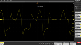
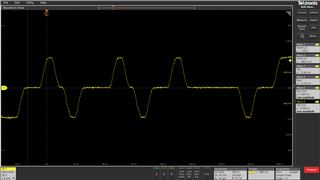
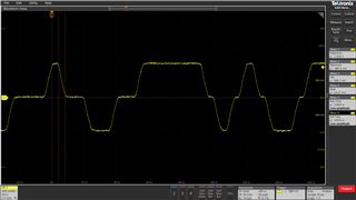
    With the above, we captured the TX signals for both the ethernet channels and found to be within 1.05V. They are as per the spec now and passing.

    Channel 1 TX:

    Channel 2 TX:

  • Hi Premalatha,

    Thanks for the update.

    --
    Regards,
    Gokul.