Part Number: TUSB216
Other Parts Discussed in Thread: , TUSB215
Hi expert,
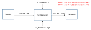
I am using the TUSB216RWBR as shown in the diagram.
Connecting a 4m camera and a 1.5m LTE dongle to TUSB216.
In this state, communication passes at BOOST Level 0, and communication fails at BOOST Level 3.
BOOST Level 0 → USB communication PASS
BOOST Level 3 → USB communication FAIL
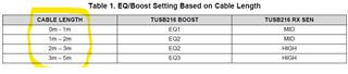
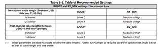
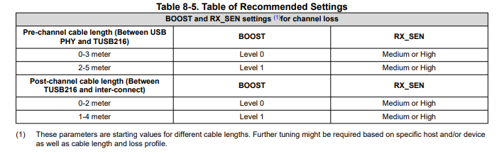
■How do you calculate BOOST Level and RX_SEN ?
■What is the optimal BOOST Level when using 4m and 1.5m cables ?
■What is the optimal RX_SEN when using 4m and 1.5m cables ?
Please let me know.