Part Number: TMDS442
A customer is trying to integrate our display and is having intermittent video issues. We determined that a digital decoder, which is downstream of the TMDS442 switch is not is not locking onto the TMDS when the display is in a failed state. The video typically fails when the display is cold and then reliably works once it has ran for a while.
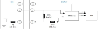
In our design we have the HPD1 output through a 953 ohm series resistor back to the source. We found that adding a pull-up resistor from HPD1 to the +5V source has resolved video failures, but we our looking for explanation.
Our hypothesis is that our customer's systems is too much of a load for the TMDS442 HPD driver. Something unusual that we noticed is that the HPD voltage drops with higher loads and that the HPD current is much higher when the 1K Ohm PUP is connected. The customer's SBC consumes more current that our video pattern generators, which haven't had any failures.
Could this indicate the HPD1 driver is struggling and could this affect the TMDS video?
HPD Current Measurements
|
Configuration |
HPD Current |
DVI_+5V |
DVI_HPD (V) |
Power |
|
With 1K Ohm PUP (R901) to +5V + SBC |
2.188 mA max Current high when display is turned on before settling to 0.5 mA |
4.7V |
3.8V |
8.3 mW |
|
0.5 mA nominal while running * customer reports 0.75 mA with display integrated into complete system |
4.7V |
3.8V |
1.9 mW |
|
|
Without 1K Ohm PUP (R901) + SBC |
0.385 mA max |
4.7V |
2.8V |
1.08 mW |
|
0.381 mA nominal while running |
4.7V |
2.8V |
1.07 mW |
|
|
Without 1K Ohm PUP (R901) + Pattern Generator |
0.301 mA max |
4.8V |
3.0V |
0.9 mW |
|
0.300 mA nominal while running |
4.8V |
3.0V |
0.9 mW |
I wasn't clear from the datasheet on what the current limits were for this particular pin and could use some clarification on it.
Other:
3 of the 4 source inputs are used and both sink outputs are connected. The unused source input pins were left open as recommended.
Thank you.
Edit:
Gave better configuration descriptions in table