This thread has been locked.

If you have a related question, please click the "Ask a related question" button in the top right corner. The newly created question will be automatically linked to this question.

THVD1510: Inquiry Regarding Replacement of THVD1510DR

Part Number: THVD1510
Other Parts Discussed in Thread: THVD1520, THVD1420

Hi, TI expert.

The customer would like to replace the currently applied RS-485 Transceivers to TI components(THVD1510DR).

(Existing) SP485EEN (Maxlinear) → (Replacement) THVD1510DR (TI)

SP485EEN_Datasheet(Maxlinear).pdf 

Both are in SOIC-8 packages and are pin-to-pin compatible.

Below is the currently applied circuit diagram.

The customer wants to use the existing PCB board by changing only the parts from SP485EEN (Maxlinear) → THVD1510DR (TI) without changing the peripheral circuits.

Q1) Is there any potential issue with using the THVD1510DR as a direct replacement for the RS-485 Transceivers IC without modifying any of the surrounding components?

Q2) Alternatively, might there be a need to modify the surrounding components?

Q3) Should we proceed with testing the THVD1510DR on the PCB board as a sample to confirm its compatibility?

Please provide guidance on this matter.

Thank you.

  • The THVD1510 is fully backwards compatible; no changes are required.

    The THVD has fully fail-safe inputs. If there are no other receivers without fail-safe inputs on the bus, R50/R51 might no longer be necessary.

  • Hi Grady,

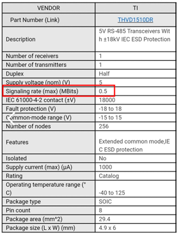
    First - you should probably use the THVD1520 as the Maxlinear device is rated to 10Mbps which is the same data rate as the THVD1520 - and the THVD1510 is only rated for 500kbps  - sot he THVD1510 is not the best replacement unless the system only needs 500kbps or less for its data rate - than the THVD1510 is okay. 

    For your direct questions:

    1. The THVD1510 might be too slow; but the THVD1520 should work in the same situation as Maxlinear device; generally speaking the two terminal (end) nodes on the differential bus should be terminated with 120 Ohm resistors and we generally wouldn't suggest 47 Ohm series resistances (usually 10 to 22 if used at all) - however if this is already working with Maxlinear device I don't think there would be issues switching over to the THVD1520. I will also note that the THVD1420 is also an option and does perform a bit better than the THVD1520. 

    2. If the Maxlinear device currently works in this configuration I don't see any reason that the the THVD1520/THVD1420 couldn't work - as noted in the point above there are some general schematic critiques - but ultimately  if this works already than using the THVD1520/THVD1420 should produce similar results. Also the THVD parts that I mentioned do have a higher bus fault rating - so the diodes can handle a bit more current before damaging TI's device compared to Maxlinear. 

    3.  Testing is always a good idea to confirm - but I would look at the THVD1520 or THVD1420 unless you only need a data rate of 500kbps or less - as that could present an issue with compatibility between the current system and the behavior of the THVD1510. 

    Please let me know if you have any other questions!

    Best,

    Parker Dodson

  • Hi, Parker

    I have additional questions.

    The signaling rate max value of THVD1510DR is 0.5 Mbits.

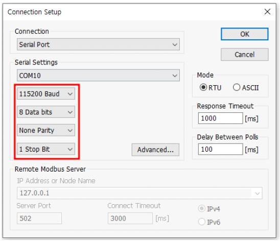
    The communication environment used by the customer employs RS-485 Modbus-RTU protocol for communication.

    9600~115200 Baud
    8 Data bits

    When the baud rate is 115200,   115200 * 8bit = 921600 => Signaling rate 0.9216MBits

    When the baud rate is 57600,   57600 * 8bit = 460800 => Signaling rate 0.4608MBits

    Q1) Based on the calculations above, it appears that a Baud rate of 115200 cannot be used. Please verify if this is correct.

    Q2) The maximum confirmed communication speed used by the customer is 9200bps, with some special models using 115200bps.

    Out of a total of 84 models, 95% use 9200bps, and 5% use 115200bps.

    Therefore, is it acceptable to use THVD1510 for the 9200bps models and THVD1520 for the 115200bps models?

    2. May we also request a circuit review in addition?

    1) This is the circuit diagram that was previously implemented using SP485EEN.

    We are considering incorporating the THVD1510 (TI) component into all models and would like to request a review to determine if there are any modifications needed in the current circuit or if any additional components need to be added.

    (Please refer to the attached documents for reference).

    3. The circuit diagram below is intended for implementation in a new model.

    We kindly request a review of the circuit diagram, taking into consideration communication/surge/ESD, etc.

    (Please refer to the circuit diagram below for reference).

    Please check. Thank you.

  • Q1) These calculations are wrong. The baud rate is already measured in bits, so 115200 baud = 115200 bits/s. With the 8N1 framing, each byte has one start and one stop bit, so the maximum data rate would be 115200 bits/s / 10 bits/byte = 11520 bytes/s.

    Q2) You can use the THVD1510 for all models.

    2.1) No circuit changes are necessary. (The THVD1510 has better ESD protection than the SP485E, but this does not affect the other electrical characteristics.)

    3. Looks OK.

  • Hi Grady,

    1. I do believe the baud-rate (symbol rate) and bit rate are the same in Modbus -so 115kbps is is 115kbps not 115kbps * 8. The 8 just is defining the packet length for higher level functionality of Modbus - the transceiver doesn't care about packets at all - it only cares about the bit rate which should be the baud rate for Modbus. Using a faster part like when you don't need to can add to higher frequency energy to the system which could cause higher risks of emissions/ SI issues. 

    2. You should be able to use THVD1510 for all use cases. If you are still hesitant you can use the THVD1520 for the 115kbps signal - but its probably not necessary to have two different solutions - as the bit rate should be 115kbps. 

    3. It looks like you just replaced the IC from the original design and if the original design worked I don't see a lot of issue using the THVD device in its place.

    Generally its best practice to have both start and end nodes terminated from A to B with 120 Ohm resistors - this is to mitigate signal reflections (when paired with a 120 Ohm characteristic impedance cable). If the system is unterminated a device like the THVD1510 when operating at its fastest (w.r.t. to signal transition time) and assuming cable is has a signal propagation of 78% c (it can differ - but for RS-485 type cables 78% c is pretty normal for the value) you can get like 7 meters before you will start having signal reflections - nominally this would increase to about 9.3 meters are room temp operation. However the MaxLinear device you have right now would start reflecting, in the same conditions, at ~1/3 of a meter (it is much faster device). So you may see a less noisy bus by switching to the THVD1510 or very similar if you use the THVD1520. 

    I don't know what the main purpose of the D10 and D11 diodes are as the D12 diode array will be conducting at its max voltage level at less than the working voltage of D10 and D11 - so I don't know if these are adding much value as the fuse would probably blow before D10/D11 are clamping very much during a fault - so you are just adding bus capacitance. Essentially we don't usually see two pairs of protection diodes in parallel like this - while I don't think it would necessarily  cause issue with function - protection isn't usually done like this. 

    Ultimately if this system has worked with the other device I don't really see a reason why the THVD devices also wouldn't work - I don't believe it to be fully optimized for best performance - but it should work still. 

    Please let me know if you have any other questions.

    Best,

    Parker Dodson