This thread has been locked.

If you have a related question, please click the "Ask a related question" button in the top right corner. The newly created question will be automatically linked to this question.

AM26LS31C: AM26LS31 TO HCPL2430 INTERFACE query

Part Number: AM26LS31C
Other Parts Discussed in Thread: AM26LV31, AM26C31

Hi,

Quick question related to AM26LS31CDBR part, Is there a possibility of difference in the channel to channel propagation delay ?

Should we assume it is going to be same for both channels 7ns?

Clarification required in the following scenerio : 

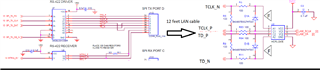
In the following schematic image :

  • RS422 driver part # AM26LS31CDBR (New Transmitter board)
  • Driver is connected to receiver input section with 12 feet LAN cable
  • HCPL-2430-300E opto coupler is used on the receiving side (Legacy receiver design)

Presently we do not have an option to modify our legacy receiver designs.

Am reaching out to understand scenerio's like if i have differential transmitter to differential receiver type design, typically a ground reference might be needed between both transceivers.

While in the above case, on one side we have RS422 Transceiver, while on the receiving side it is being received with an opto coupler, am worried about the consistency to meet the CRC checks.

Reasons : 1.) SPI clock being used is 10Mhz, the opto coupler has propagation delay of 35ns typical value(under 50 Centigrade)

2.) if there is no ground reference between Transmitter to Receiver end, is there a possibility of mis interpretation on the receiver end due to differences in the differential voltage?

One of the reasons to reach out is, As we are using AM26LS31CDBR on the transmitter side, Is this going to be an issue reliability point of view about the consistency(prone for CRC errors) due to above reasons?

Appreciate your inputs and feedback.

  • You do not need a ground line. The optocoupler inputs are galvanically isolated (i.e., floating); not having a common ground is the whole purpose of using an optocoupler.

    The transceiver is faster than the optocoupler. I do not see it introducing additional timing problems.

    The AM26LS31C is being discontinued. Use the AM26C31 (or the AM26LV31 with a 3.3 V supply), with higher speed and lower power consumption.

  • Hi Vinay,

    1.) For the speed question - the optocoupler is slower, so I don't see an issue with the driver. 

    2.) As Clemens mentioned you don't need to ground line because the optocoupler is adding isolation to the system - so no common ground is part of using the optocoupler.

    Also the AM26C31 is most likely the best choice because the other device is being discontinued so it will be off market - they are pin to pin I believe so it shouldn't require board modifications. 

    Please let me know if you have any other questions!

    Best,

    Parker Dodson

  • Recently I did capture the differential output signal at the output of the part AM26LS31C.

    We did observe there is a delay of ~8ns between clock and data, it's definitely unclear if this failure or issue is due to any ESD impact on the device itself or any other part specific issue?

    We did replace RS422 driver IC, which had both clock and data aligned perfectly with no delay.

    CRC error did not re occur and resolved.

  • HI Vinay,

    Okay - so did you replace the RS422 driver with the AM26C31 or did you replace it with another AM26LS31C?

    Best,

    Parker Dodson

  • As the old part AM26LS31CDBR got obsolete, we replaced with AM26C31IDR

  • Hi Vinay,

    Thanks for the clarification - since you haven't seen a issue after the part switch; I think the design looks okay with new part.

    Please let me know if you have any other questions!

    Best,

    Parker Dodson