This thread has been locked.

If you have a related question, please click the "Ask a related question" button in the top right corner. The newly created question will be automatically linked to this question.

TCA9511A: System level issues with I2C Failures

Part Number: TCA9511A
Other Parts Discussed in Thread: TCA9548A, , TCA9406

Hello,

I have a system that looks roughly like the following block diagram.

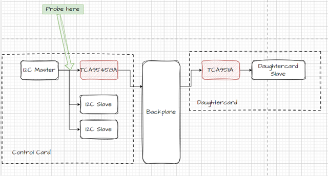
  1. I issue a command to TCA9548A to disconnect all downstream channels (write 0 to 0x70)
  2. I write some data to an I2C Slave on the Control Card. Successful.
  3. I issue a command to the MUX to attach the shown Daughter Card (write 1 to 0x70)
  4. I repeat the command from Step 2. Failure.
  5. I repeat the command from Step 1. Success.
  6. I repeat Step 2. Success.

It appears that connecting the Daughtercard to the bus causes errors to occur on the Control Card bus. Note that I have no problems talking to the Daughtercard Slave device when it is connected.

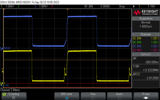
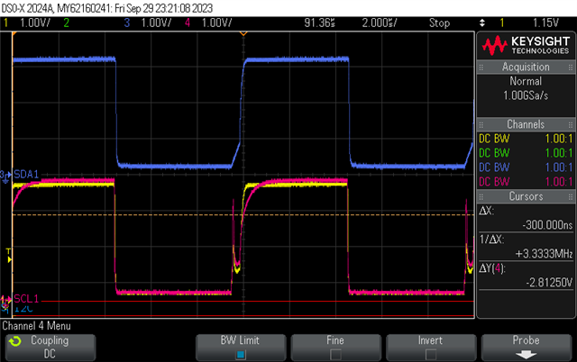
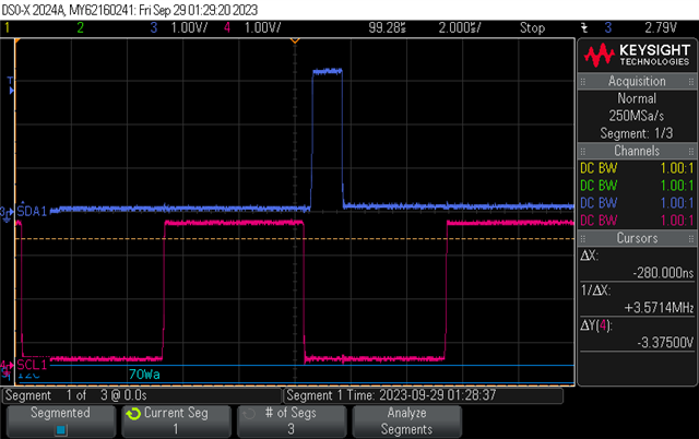
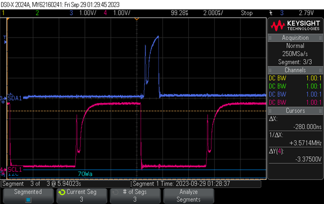
In the below scope captures, Pink is SCL, Blue is SDA. I have indicated the probe point in the block diagram. The below captures are the exact same commands sent to the bus. In Image 1, the daughtercard is not connected. In Image 2, the daughtercard is connected. 

Any help troubleshooting is appreciated. 

Thanks,

Michael

  • Hi Michael,

    With the addition of the daughtercard, are there any more pull-up resistors or other sources of pull-up current on the daughtercard board? About how much parasitic capacitance do you think is added to the I2C bus when you connect the daughtercard? 

    It looks like the RTA's of the TCA9511A are firing prematurely. RTA looks to be turning on, causing a fast rising edge to VCC, but the output side of the 9511A is still being driven LOW, so the RTA on the input side eventually turns off and is driven back to a lower voltage before being released because the output side is catching up. Then the SCL1 is able to rise to a VCC. 

    Regards,

    Tyler

  • Hi Tyler,

    There are 10k pull-ups on the OUT side of the TCA9511A (IN side is connected to backplane). I'd estimate maybe 100pF or more when daughtercard is connected. The trace on the backplane is ~35cm in length. Also, I am running the bus at 100kHz. 

    I was wondering if the RTA had something to do with it. Do you have a recommendation for fixing this?

    Thanks,

    Michael

  • Hi Michael,

    Are there pull-up resistors present on the input/output of the TCA9548A? 

    Also if you want to send a full schematic to my email, I can take a look at it from my end. That way it is not posted to the public forum. 

    t-townsend@ti.com 

    Regards,

    Tyler

  • Hi Tyler,

    Yes, there are pull-up resistors at the output of the TCA9548A. Each of the channels has a 4.7k pull-up to VCC. At the input of the TCA9548A, there are (I believe) 10k pull-ups.

    I'll try to maintain conversation here as long as possible so others can benefit in the future! 

    Thanks,

    Michael 

  • Hi Tyler, 

    Minor correction. The input side of TCA9548A has 4.7k pullup resistors. 

    Thanks,

    Michae

  • Hi Michael,

    The TCA9548A is a passive device, meaning that when the input and output are enabled and connected together, the only element separating the two sides is a passive FET that is ON during a low transition. This means that upon rising to a VCC, the input & output sides pull-up resistance will appear in parallel. 

    If input side has 4.7k, output side has 4.7k, the effective pull-up resistance is 4.7k || 4.7k = 2.35kohm. I recommend increasing the pullup resistance of these two resistors. Is it possible to use something like 10kohm on both sides? I believe the pull-up strength is too strong, the rising edge is too fast, and the VOL is large, possibly causing a false trigger on the RTA. 

    Is push-pull driving being used in this system? 

    For the SDA channel in the scope captures, is this expected behavior on your end? I2C usually requires that SDA be stable for the duration of the high clock period. 

    Are you able to gather scope captures of the input and output sides of the TCA9511A? 

    Regards,

    Tyler

  • Hi Tyler,

    I can easily change one of the 4.7k resistors to something higher. The input side of the TCA9548A might be trickier. I also am not sure if push-pull is being used as there is a level translator block on the master device and I don't have access to the part number. I have asked for more information from the vendor about that.

    Yes I believe that is the expected behavior on SDA. I think we are looking at the ACK bit. 

    I can grab scope captures of both sides of the TCA9511A, give me a few moments to get the test setup.

    Thanks,

    Michael

  • Hi Tyler,

    Here are the captures of before and after the TCA9511A.

    In this image, blue is on the OUT side of TCA9511A so on the daughtercard side. Yellow is IN side, so backplane side. Also this is SCL.

    Same as above, but pink is SCL captured on the control card side, so IN of TCA9548A. One thing to highlight is the magnitude of the initial rise is larger on the control card than on the daughtercard.

    TThanks,

    Michael

  • Hi Tyler,

    I believe TCA9406 is the level translator on the master device, but I am awaiting confirmation. 

  • Hi Tyler,

    I've attached a PDF to show a quick comparison of the SCL line with different pullup values at the output of TCA9548A. It looks like there is not much difference between 11k and 100k, I know I'm ultimately limited by the pull-up resistor on the master device side, but I don't know that I can change that.

    pullup_comparison.pdf

  • Hi Michael,

    Thank you for the additional information and pullup comparisons. At this point, I definitely believe it has something to do with the overall drive strength of the I2C bus which is adding to the effect of the RTA triggering when it is not suppose to. 

    I've attached a PDF to show a quick comparison of the SCL line with different pullup values at the output of TCA9548A. It looks like there is not much difference between 11k and 100k, I know I'm ultimately limited by the pull-up resistor on the master device side, but I don't know that I can change that.

    I suspect that there is not much difference between 11k and 100k pull-up resistors because there are stronger pull-up resistors present on different parts of the bus. If you have a singular 4.7kohm pull-up resistor, and somewhere downstream you change 3 pull-up resistors to 100k, the effective pull-up resistance is still ~4kohm. If you are using the TCA9406, there are internal 10kohm pull-ups on both sides of the device that can't be turned off. So already there is 10k || 10k = 5k. 

    Speaking of the TCA9406 you said...

    I believe TCA9406 is the level translator on the master device, but I am awaiting confirmation. 

    So there is a TCA9548A, TCA9511A, and TCA9406 all present on the bus? Can you confirm this? I am wondering if the RTA of the TCA9406 is causing issues with the RTAs of the TCA9511A. Signal is rising too fast for the input side, and the output side is having a hard time catching up to the trigger point. 

    Also can you confirm on whether or not push-pull is being used, and if so, is there a possibility to reduce the drive strength of the drivers especially when pushing to VCC? 

    Do you have a complete schematic on hand that you could send to my email? t-townsend@ti.com 

    ON The backplane input side, what is the VOL (yellow waveform) and what is the VOL of the input TCA9548A (pink waveform)? 

    Regards,

    Tyler

  • Hi Tyler,

    I suspect that there is not much difference between 11k and 100k pull-up resistors because there are stronger pull-up resistors present on different parts of the bus.

    Agreed. This was my thought as well.

    So there is a TCA9548A, TCA9511A, and TCA9406 all present on the bus? Can you confirm this?

    I am waiting to hear from the supplier of the master device to confirm the part that it is indeed the TCA9406.

    Signal is rising too fast for the input side, and the output side is having a hard time catching up to the trigger point.

    Yes, this was my next thought as well I suppose I can test this by getting a different I2C master device and issuing the same commands. I should be able to get my hands on one easily today.

    ON The backplane input side, what is the VOL (yellow waveform) and what is the VOL of the input TCA9548A (pink waveform)? 

    Yellow VOL looks about 150mV. Pink VOL looks about 100mV.

    Thanks,

    Michael

  • Hi Michael,

    I am waiting to hear from the supplier of the master device to confirm the part that it is indeed the TCA9406.

    Thank you for looking into this. 

    Yes, this was my next thought as well I suppose I can test this by getting a different I2C master device and issuing the same commands. I should be able to get my hands on one easily today.

    Please let me know the results of this testing. 

    Yellow VOL looks about 150mV. Pink VOL looks about 100mV.

    The VOLs are well below the 0.6V trigger level. So I would assume that noise would not cause a false trigger on the RTA. 

    Regards,

    Tyler

  • Hi Tyler,

    Left/soft edges are with a master device without translator and with I think 2k pullups. Right/darker edges are when the original master device is used. 

    Still awaiting confirmation of the part number of the level translator but it does look like there is some rise time battling happening.

  • Hi Michael,

    The soft edge case looks to have improved signal quality over the original master device. 

    Looking forward to knowing what device is on the I2C bus. 

    Is there an available schematic on hand? I have been asking about it in the previous threads with no response to this request. 

    Regards,

    Tyler

  • Hi Tyler,

    The device is indeed TCA9406. 

    I am still determining if I am able to send schematics externally. Is there anything specific you're interested in seeing that I can clarify? 

    Thanks,

    Michael

  • Hi Michael,

    If it helps, you can send it to my TI email here: t-townsend@ti.com. This way we can keep the conversation off the public forum. 

    The reason I am interested in the schematic is that there is a mention of the TCA9406, but the functional block diagram does not show this device. I am wondering what I2C level translators, switches, other devices, etc. are on the bus that could potentially be left out from a block diagram perspective. I think I would have a clearer idea of all the connections if I was able to look at the schematic in something like pdf format. Most of our customers are able to share pieces of their schematic, and it helps tremendously if there are in .pdf so I can search for the specific part numbers. 

    Like we talked previously, it looks like there is issues with the RTA's triggering / conflicting. 

    With the additional information of a TCA9406 being present, there are now two sets of RTAs on the I2C bus along with the TCA9511A, and pairs of pull-up resistors located in different parts of the bus. I have a feeling since there is an I2C switch present TCA9548A, that there is some delay between the two sides of the device due to parasitic capacitances that is causing a false trigger on RTA's when the otherside has not been released yet. Where is the TCA9406 located in the functional block diagram? 

    In most of our devices, the RTA's only trigger for a certain time towards VCC before turning off. I believe they pull towards VCC about 90% of the way before beginning to shut off, this way they don't ring the voltage at the top. Therefore, if there is considerable amounts of delay between the two sides of an I2C device such as the TCA9511A hot swap buffer, then I could see the circumstance where RTA is driving high while the other side is still releasing from an output low. 

    Do we have the datasheets for the different master devices that were used? 

    Also if it helps, I would be available for a call early tomorrow if that is easier to explain this issue? This problem seems to have multiple layers. I think overall, I am having trouble understanding the location of the I2C devices mentioned, as well as where the scopes are being probed within the system. 

    Regards,

    Tyler

  • Hi Tyler,

    I will send you an email. 

  • Hi Michael,

    I will close this thread since I got your email. Looking through your email now and will respond soon. 

    Regards,

    Tyler