This thread has been locked.

If you have a related question, please click the "Ask a related question" button in the top right corner. The newly created question will be automatically linked to this question.

TUSB212: How long PCB trace can be route after the USB re-driver?

Part Number: TUSB212
Other Parts Discussed in Thread: TUSB213, TUSB216I, TUSB211A, TUSB211, TUSB216

Hi TI Experts

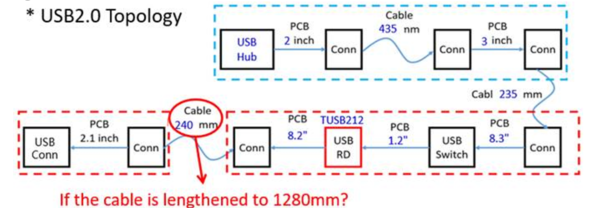
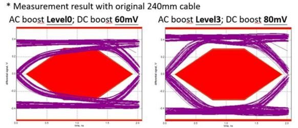
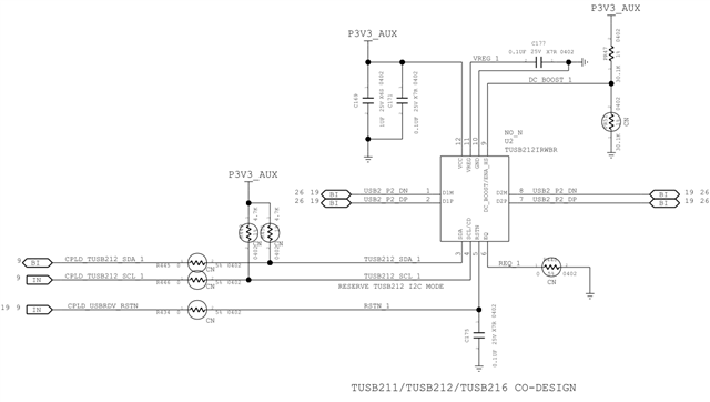
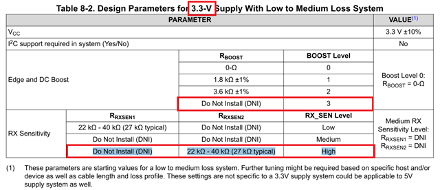
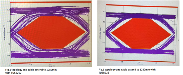
We route long USB trace before the redriver from CPU. We test failed when SIV test ,after we change AC boost to Level3 and DC boost to 80mV then test result is pass ,but test margin is not much.

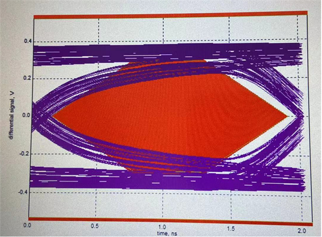
Now we have new design requirement and it will increase USB PCB trace and cable length. We need to estimate the risk about this design change. 

Do TI have recommand trace length after USB re-driver?
Do TI have SI simulation model for TUSB212?

Thanks.

  • Hello,

    Do TI have recommand trace length after USB re-driver?

    We do not have any specified recommended trace length for before or after the redriver. In general, we recommend a max cable length of 5 meters between a host and the device. Past 5 meters, we recommend adding on a redriver to the signal. In the case of the TUSB212, we spec the post-channel cable length at 2 meters, meaning for those 2 meters after the TUSB212, the signal should be stronger than it was as it entered the redriver. 

    For more info on layout, I would recommend looking at our High-Speed Layout Guidelines for Signal Conditioners and USB Hubs Application Note.

    Do TI have SI simulation model for TUSB212?

    TI Does have H-spice models for the TUSB212/TUSB213. If you have an NDA with TI, please let me know what the NDA ID is and accept my E2E friend request, and I will get that sent over to you for use. 

    If possible, could you send over a block diagram of your system, indicating lengths between the Host, redriver, and device, or any other boards in between the host and device? I would like to understand what the general layout of this system is. Please let me know.

    Thanks,

    Ryan

  • The Fig.1 is our USB2.0 topology, including TUSB212. The Fig.2 is the measurement result. The eye diagram is passed if using AC boost Level3 and DC boos 80mV. If we would like to change one of the cable length from 240mm to 1280mm, can you help to check the risk? If it’s risky, can you provide any suggestion? (Change Redriver or others…)

    Fig.1

    Fig.2

  • Hello,

    Currently, the eye does look good, but adding an additional meter does have the potential to degrade the signal to where it is failing the test, especially since you are already at the max settings.

    One thing I would recommend is switching from the TUSB212 to the TUSB216I. Its one of our newer redriver devices, and has additional means of compensation, such as RX Sensitivity settings for ISI jitter and high-lose applications. Additionally, I2C can be used on the TUSB216I to allow for higher levels of DC or AC boost if needed.

    Another thing you could do, if needed, is add another TUSB212 onto the path, after the added cable length, near the connector. This would help to improve the signal as well.

    Please let me know if you have any other questions.

    Thanks,

    Ryan

  • Hi Ryan

    I checked the TUSB216I datasheet ,it seems pin to pin compatable with TUSB212.

    I have few question about TUSB216I.

    1. Is TUSB216I already MP? May I request some sample to verify?

    2. You mention the high loss applicaiton and I see the Table8-1 in spec. Is the high loss application only support when VCC=5V? If use VCC=3.3V ,the re-drive capability is still stroger than TUSB212?

    Thanks.

  • Hello,

    1. Is TUSB216I already MP? May I request some sample to verify?

    The TUSB216I has already been released, yes. For samples, I would recommend reaching out to your local FAE, or, scrolling down on the TUSB216I webpage, and selecting the request samples option here under "Ordering & quality" on the TUSB216I TI page:

    Additionally, for a lower-cost alternative, I would recommend looking the TUSB211A. Its a new low-cost spin of the TUSB211 which has better noise performance compared to the TUSB211. There should be samples available for this device as well.

    2. You mention the high loss applicaiton and I see the Table8-1 in spec. Is the high loss application only support when VCC=5V? If use VCC=3.3V ,the re-drive capability is still stroger than TUSB212?

    Yes, even at 3.3V, the TUSB216I should still be able to compensate for more loss than the TUSB212, thanks to the RX_SENS pin.

    Additionally, for that table 8-1, please note the footnote specifying that these settings are not only for a 5V system, but may also be applicable for a 3.3V system.

    Please let me know if you have any questions!

    Thanks,

    Ryan

  • Hi Ryan,

    We got TUSB216I sample yesterday and we rework on our board to verify.
    As Fig. 3 is the measurement result, it look worst then TUSB212IRWBR(Fig. 2 right).

    Fig. 4 is schematic design same as TUSB212IRWBR solution.
    Fig. 5 is the TUSB216I spec, the EQ value is the maximum.
    It urgently to us, could you help to check?

    Fig. 3

    fig3fig4fig5

  • Hello,

    Looking at this eye diagram you sent, figure 3, it seems like the redriver is not turning on. Would you be able to monitor the signals on the CD and ENA_HS pins and see if they are reading as high or low? If the redriver is enabled, then both these pins should be outputting a high signal of at least 2.5V.

    For the schematic, if pins 9 and 6 are meant to represent RX_SENS and BOOST respectively, then the design seems correct. One thing to note is that it may be better to start at lower RX_SENS and BOOST levels to avoid passing the disconnect threshold, but for now while we are trying to ensure the redriver is enabled, we can focus on the CD and ENA_HS pins.

    For testing, please ensure you are following the instructions outlined in our TUSB21xx High-Speed Signal Quality Test Modes Application Note.

    Please let me know what you find on those CD and ENA_HS pins, and we will work from there.

    Thanks,

    Ryan

  • It look hw rework problem. After rework again we use Fig1 topology and extend cable to 1280mm then compare the result.

    The TUSB216(right) better then TUSB212(left) but not have enought margin, does the schematic hw strap could adjust more ? thanks

  • Hello,

    Good to see that the device is working. Is this done with the settings as listed in your previous post, BOOST level 3 and RX_SENS level high?

    The TUSB216I does have I2C registers which, if you want to use them, can go past the levels of boost and RX_SENS provided by the pinstrap of the device.

    Additionally, another redriver, such as a TUSB212, can be added closer to the hub/host side of the system to help boost the signal.

    Looking at the TUSB216I eye you sent, it seems like the main issue is DC Boost needs to be high. An added TUSB212 in tandem with the current added TUSB216I can specifically boost the DC aspect of the signal while leaving the AC component of the signal relatively unboosted, or you can use the I2C registers on the TUSB216I to increase specifically the DC Boost of the TUSB216I past the pinstrap settings.

    Please let me know!

    Thanks,

    Ryan