This thread has been locked.

If you have a related question, please click the "Ask a related question" button in the top right corner. The newly created question will be automatically linked to this question.

TCA9511A: Data rate not as expected

Part Number: TCA9511A
Other Parts Discussed in Thread: TMS320F28386D

Hello,

We are using the TCA9511A to interface our TMS320F28386D with an I2C sensor :

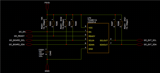
We observe the following I2C waveforms:

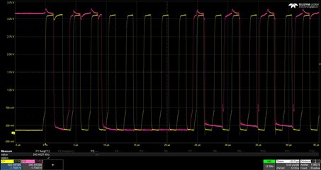
We were suspecting the I2C pull-ups so we aready changed from 10k to 3k22 on the input side without reaching the expectations (configuration of the screenshots) after carefully following the I2C Bus Pullup Resistor Calculation appnote.

On the board side, we have something like 10cm of PCB track.

On the external side, we have something like 20-30cm of PCB + wire.

Best regards,

Clément

  • These waveforms look OK. What is the problem?

  • The C2000 is configured at a bitrate of 400kbit/s.

    The observed clock is not at the right frequency.

  • The TCA9511 does not change the clock timing.

    How exactly have you configured the C2000's I²C clock?

  • Hi Clement,

    TCA9511A does not change the clock frequency as Clemens already mentioned. 

    How has the C2000 clock been configured? Do you notice a change in fSCL if the TCA9511A is removed? 

    Regards,

    Tyler

  • Hi,

    We can't really remove the TCA9511A as easily and get the sides to be interconnected.

    The C2000 is running at 200MHz sysclk and we are using the driverlib function I2C_initMaster with the sysclkHz parameter set to 200000000 and the bitRate parameter set to 400000.

    What I can't understand, as highlighted on the above screenshot in red, is that behavior on the rising edge which is where I think the issue is.

    The red straight line is how I would have expected the rising edge to be.

    If you measure the time between the straight rising edge on the yellow signal and the end of the falling edge, the delay is 2.5µs which correspond to the 400kHz.

    And indeed, the issue does not seem to be fully related on the TCA9511A as we have a similar waveform on the TCA9511A input.

    We were suspecting the I2C pull-ups and changed them after carefuly recomputing the values following your app note but the frequency is still not correct.

    Best regards,

    Clément

  • In order to detect clock stretching or multi-master conflicts, the C2000 reads the I²C lines back and waits until they have actually gone high. (In theory, all I²C masters are required to do this.)

    You could use stronger pull-up resistors, but I do not think that this is a problem that would need solving.

  • This is what I was thinking.

    You mean decrease the pull-up value to a value closer to Rpmin ?

    If you don't consider any real-time constraint of the application, for sure it would not need solving.

    However, as the exchange duration is longer than what we expect, this becomes a problem for us. 

  • You mean decrease the pull-up value to a value closer to Rpmin ?

    Yes, this would create a 'stronger' pull up resulting in faster edge rates. 

    I believe what you're seeing is just the TCA9511A distorting the duty cycle of the clock, I would guess that if you measured the actual period, you would see around 400kHz but the clock lows would be longer than expected because the signal is rising slower and the rise time accelerators have not turned on yet to generate the high period. (I2C fall times are faster than rise times so generally 'low periods' are longer than 'high periods' in I2C)

    -Bobby

  • Bobby,

    We are going to try that.

    I am not sure about the second part of your message, we measured the transmission times by software and we are not getting the 400kHz.

    Thanks for the detailed explanations.

    Clément