This thread has been locked.

If you have a related question, please click the "Ask a related question" button in the top right corner. The newly created question will be automatically linked to this question.

DS90UB954-Q1: Channel requirements for 4Gbs, PoC recommendation and simulation

Part Number: DS90UB954-Q1

Hi expert,

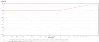
I'm using Des-954 paired with Ser-943.(4Gbs mode) Even if I use the PoC components recommended by TI D/S, it cannot pass the simulation. Simulation result shows that S11&S21 will fail at 1MHz~2MHz. 

The 10uH inductor is too small to block 1MHz signal. In comparison, the recommended 100uh inductor in 2Gbs mode looks more reasonable, but why do their simulations requirement to be the same? They all start from 1MHz and the limits are the same.(channel spec: FPD3_91X_93X_95X_96X-Channel-Requirements-ADAS chipsets-0.8.1)

I checked the layout and it looks good, smooth and within 2 inch. And the failure position is at low frequency. I think this depends on the large inductor.

So, could you help pass this simulation and answer some questions:

  1. The recommended PoC components also fails the simulation. Does TI have a simulation report?
  2. Why does the simulation require starting from 1MHZ? It seems very strict.
  3. The requirements for 2G and 4G modes are the same (except for the cutoff frequency), but the recommended PoC structures are different?

Best regards,

Harvey Nie

  • Hi Harvey,

    The recommended PoC components also fails the simulation. Does TI have a simulation report?

    We do not have a simulation report for these networks. The results will vary depending on the system design. 

    Why does the simulation require starting from 1MHZ? It seems very strict.

    In the channel specifications, we list the insertion loss and return loss requirements for the entire possible frequency band that the FPD-Link devices may operate in. However, you only need to meet the requirements for the specific frequency band that your system will use. The operating frequency band is half of the back channel frequency to the forward channel frequency (nyquist). Depending on the devices you are using and the operating mode they are configured for, the frequency band on the channel will vary. 

    For example, if 954 has a 25MHz REFCLK and is paired with 953 in synchronous mode, the back channel frequency is 50MHz, and the forward channel frequency is 2GHz (4Gbps line rate). Therefore, the system must meet the channel specs from 25MHz-2GHz. If 954 will only ever pair with 953 in sync mode, you can design the channel and PoC network to meet the channel specs for this specific frequency range. If a different camera module with a different serializer will be connected to the 954, then you may have to account for a lower back channel frequency.

    The 1MHz frequency values corresponds to the lowest possible back channel frequency that is generated when connected to a DVP serializer, such as the DS90UB913A or DS90UB933. You only need to meet the insertion loss and return loss limits for as low as 1MHz if you plan on connecting a DVP serializer to the deserializer in your system. If you do not plan on operating in DVP mode at all, you do not need to worry about the results in the 1-2MHz range. 

    The requirements for 2G and 4G modes are the same (except for the cutoff frequency), but the recommended PoC structures are different?

    The PoC network must effectively filter across the entire operating frequency band. The 2G and 4G networks are different because they are filtering different frequency bands based on the connected serializer. The datasheet shares what frequency range is being filtered by each network. 

    The channel specifications vary based on device pairing and operating linerates. You can check for this information at the top of each page in the channel specs document. 

    The RF parameters for the total channel must be met for the frequency band of the system. The channel specs also includes PCB and cable budgets in case you are designing only one part of the total channel. Note that the PoC network contributes to the PCB loss.

    Regards,

    Cindy

  • Hi Cindy,

    Thanks for your quick reply. Actually I am facing a complex issue where the software detects camera data frame error. Although many tests were done on the hardware, such as MAP and total channel S-parameters, they all passed. But I'm still challenged because the S parameters of single DES board (domain controller) did not comply with TI recommendations.

    Could you confirm that a single board can be allowed to deviate if the total channel meets the requirements?

    Best regards,

    Harvey

  • Hi Harvey,

    Yes, a single PCB board can deviate from the PCB budget column of the channel specs since that column is informative. The requirement that must be followed is the total channel requirements. 

    I also want to point out that the channel specs includes PoC network requirements. Have you done measurements to check that this is also meeting the spec?

    Regards,

    Cindy

  • Hi Cindy,

    The total channel S parameters are tested when the power is on, and the PoC network is working at this time. I got S-parameter testing guidance from TI.

    Best regards,

    Harvey

  • Hi Harvey,

    Sounds good, let me know if you have any additional questions. 

    Regards,

    Cindy

  • Well, the current software strategy is to stop working when two consecutive frames of data errors are detected, which is considered unacceptable. I have reservations about this strategy. I have no knowledge of image processing, but data errors are inevitable.

    How do you think about this strategy? This may be beyond this topic, but it is also related to "How FPDLINK ensures that data is transmitted correctly without errors"

    Best regards,

    Harvey

  • Hi Harvey,

    The way error handling is done is ultimately up to the system implementer and what your requirements are. Some systems have more stringent requirements than others.

    The 954 has error handling features where it can check for errors at the RX ports and only pass through error-free frames. You can refer to Section 7.5.9 Error Handling in the datasheet for more information. For example, you can configure the 954 to not forward CSI packets with ECC errors, or the 954 can discard video input data if it does not meet the configured PASS criteria.

    Regards,

    Cindy