This thread has been locked.

If you have a related question, please click the "Ask a related question" button in the top right corner. The newly created question will be automatically linked to this question.

DP83822EVM: DP83822 can't read and write registers

Part Number: DP83822EVM
Other Parts Discussed in Thread: TMS320F28388D

Hello,

Actually I'm using enet_lwip_udp and ethernet_c28x_config and working perfectly. I'd like to change functionality of LED_1 that is configurable and by default is not used.

Register of this led is 0x0460 and cofiguration I'd like is 0001 RX/TX Activity.

I've tried to check examples from Texas about accessing ENET registers and tried this commands:

    Ethernet_device_struct.baseAddresses.enet_base = EMAC_BASE;
    
    phyRegContent= HWREG(Ethernet_device_struct.baseAddresses.enet_base + 0x0460U);
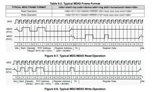
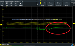
    phyRegContent= Ethernet_readPHYRegister(Ethernet_device_struct.baseAddresses.enet_base, 0x0460U);

When using HWREG i get 0x0000 when I'm using "Ethernet_readPHYRegister" I get 0xFFFF;

Actually I've tried to read other known addresses like 0x0000 to compare with datasheet default values, but no register that I read have a correspondence of values.
Using HWREG on other registers (0x0000, 0x0001, 0x0002 etc) I read "something" that doesn't correspond to datasheet default values, when I'm using "Ethernet_readPHYRegister" I get 0xFFFF any register I read.

What I'm missing?


MCU of reference is TMS320F28388D .

  • Hi Yaroslav,

    0x0460 is an extended register and cannot be accessed directly. To read 0x0460:

    • Write Reg 0xD = 001F
    • Write Reg 0xE = 0460
    • Write Reg 0xD = 401F
    • Read Reg 0xE 

    Here is a FAQ about Extended Register Reads: faq-extended-register-space-access-for-ethernet-phys

    Registers 0x0-0x1F can be read/written to directly, without having to do the bulleted steps above. If these register reads aren't matching the datasheet then there might be an issue with the way your SMI connection (MDC/MDIO) is set up or with the command you're using to access the registers. Please double check these and ready registers 0x2 & 0x3, these should match the datasheet regardless of your setup.

    Regards,

    Alvaro

  • Hello Alvaro,

    I've tried this commands (with related results):

    HWREG(Ethernet_device_struct.baseAddresses.enet_base + 0x1D) = 0x001F;
    HWREG(Ethernet_device_struct.baseAddresses.enet_base + 0x1E) = 0x0460;
    HWREG(Ethernet_device_struct.baseAddresses.enet_base + 0x1D) = 0x401F;
    phyRegContent = HWREG(Ethernet_device_struct.baseAddresses.enet_base + 0x1E);  // -> 0x0000

    HWREG(Ethernet_device_struct.baseAddresses.enet_base + 0x0D) = 0x001F;
    HWREG(Ethernet_device_struct.baseAddresses.enet_base + 0x0E) = 0x0460;
    HWREG(Ethernet_device_struct.baseAddresses.enet_base + 0x0D) = 0x401F;
    phyRegContent = HWREG(Ethernet_device_struct.baseAddresses.enet_base + 0x0E);  // -> 0x0000

    phyRegContent = HWREG(Ethernet_device_struct.baseAddresses.enet_base + 0x1); // -> 0x00A0
    phyRegContent = HWREG(Ethernet_device_struct.baseAddresses.enet_base + 0x2); // -> 0x0000
    phyRegContent = HWREG(Ethernet_device_struct.baseAddresses.enet_base + 0x3); // -> 0x0000
    phyRegContent = Ethernet_readPHYRegister(Ethernet_device_struct.baseAddresses.enet_base, 0x1);  // -> 0xFFFF
    phyRegContent = Ethernet_readPHYRegister(Ethernet_device_struct.baseAddresses.enet_base, 0x2);  // -> 0xFFFF
    phyRegContent = Ethernet_readPHYRegister(Ethernet_device_struct.baseAddresses.enet_base, 0x3);  // -> 0xFFFF

    Ethernet_writePHYRegister(Ethernet_device_struct.baseAddresses.enet_base, 0x1D, 0x001F);
    Ethernet_writePHYRegister(Ethernet_device_struct.baseAddresses.enet_base, 0x1E, 0x0460);
    Ethernet_writePHYRegister(Ethernet_device_struct.baseAddresses.enet_base, 0x1D, 0x401F);
    phyRegContent = Ethernet_readPHYRegister(Ethernet_device_struct.baseAddresses.enet_base, 0x1E);  // -> 0xFFFF

    Ethernet_writePHYRegister(Ethernet_device_struct.baseAddresses.enet_base, 0x0D, 0x001F);
    Ethernet_writePHYRegister(Ethernet_device_struct.baseAddresses.enet_base, 0x0E, 0x0460);
    Ethernet_writePHYRegister(Ethernet_device_struct.baseAddresses.enet_base, 0x0D, 0x401F);
    phyRegContent = Ethernet_readPHYRegister(Ethernet_device_struct.baseAddresses.enet_base, 0x0E);  // -> 0xFFFF

    I'm missing some kind of configuration before or privilege for this command?

    Ethernet_device_struct.baseAddresses.enet_base is 0x400C0000

    I've checked connections of clock and data, actually they're correct and correctly defined. Actually configuration of this device (using examples) is correct and works correctly, inside Ethernet_init there's already some direct configuration of PHY. Since it works well I suppose also that SMI is correct.

  • Hi Yaroslav,

    I have a few more things to check

    May you confirm that the MDIO line has a 2.2kΩ pull up resistor?

    Could you also use a Logic Analyzer to probe the MDC & MDIO lines? The MDIO STA and MDIO PHY are the same line, it's just to differentiate what is coming from the processor (STA) and what is coming from our PHY. When all F's are read, it's usually because the processor issue its read command (line goes high after) and the PHY never responds. The line is high so it "reads" all F's. When reading all 0's, its the same thing except something is holding the line down. I'm asking to use the logic analyzer to see if actual valid data is being sent.

    This figure was taken from Section 8.4.2 of the DP83867 Data sheet, but it applies to the DP83822 as well.

    Regards,

    Alvaro

  • May you confirm that the MDIO line has a 2.2kΩ pull up resistor?

    Yes, also double checked with oscilloscope if connections are correct.

    I can't figure out your pattern on my lines. I attach screenshots for each command that I send to PHY. Maybe can help you understand the problem. Especially I can't understand what happen in the last picture.

  • Hi Yaroslav,

    The pictures didn't seem to send, could you try to send them as an attachment?

    A logic analyzer makes studying these waveforms easier. It is not impossible to do it with an oscilloscope, just much more tedious. Please try sending the pictures and I can give it a shot.

    Regards,

    Alvaro

  • I'll sent them on Monday, actually I'm out of office. I can do the same captures with a logic analyzer (I don't remember if my oscilloscope have, but I can prepare an excel anyway) and send this to you.

    So actually seems no data is sent to PHY right?

    About last picture:

    What this meaning? Didn't this result in unpredictable data on analyzer?

  • Hi Yaroslav,

    It looks like the Processor is trying to communicate with the PHY, but the PHY is not responding. Looking forward to the other shots you mentioned you'd send. 

    Regards,

    Alvaro

  • Hello,

    Sorry for the delay, I add here a link to the .XLSX file.

    https://file.io/eHFsE73AtYZJ

    If you prefer by email, share with me your email by PM. If there's a better upload website, kindly share.

  • Hi Yaro,

    Our Firewall doesn't allow me to open the link you sent. I sent you a friend request so that we can chat.

    Regards, 

    Alvaro

  • I attach here the file on Dropbox in case someone want to check:

    https://www.dropbox.com/t/dFQ6kktHDTnXYcJp

    Actually problem is still not solved.

  • Hi Yaro,

    I have sent you a reply via the messages.

    Regards,

    Alvaro