This thread has been locked.

If you have a related question, please click the "Ask a related question" button in the top right corner. The newly created question will be automatically linked to this question.

TCAN1044AEV-Q1: CAN bus Biasing issue

Part Number: TCAN1044AEV-Q1
Other Parts Discussed in Thread: TCAN1044A-Q1, TCAN1043A-Q1

Hello Concern,

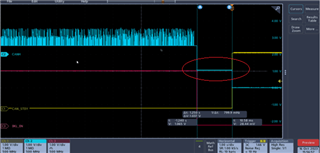
We are measuring the CAN Voltage differently during the CAN Bus Idle Condition-

Ideally, it should be 2.5V (Recessive state),

Condition is - We get a sleep command, after that for ~2 Sec - Bus is in idle State and CAN STBY will become high.

Please check the Attached image for reference.

Question is why CANH is not bias to 2.5V When in bus idle condition.

  • Shubham,

    Is there another CAN transceiver attached to the bus? Note that TCAN1044AEV-Q1 only has STB input; it does not have an EN input pin. Is it possibly turning off another device on the bus? I would not expect the CANH/CANL common-mode to bias to GND until STB = HIGH as we see in the photo, but for STB = LOW it should be biased to 2.5 V unless another device is biasing toward GND.

    Best,

    Danny

  • Hello Danny,

    thanks for the Quick response. as There is 2 Node - One is our product having a TCAN1044AEV-Q1 and other Product - We don't have a access but we will check for their transceiver. 

    If we run our product solo with CANoe tool - then we can able to Check the CAN Line biasing limited to our product?

  • Shubham,

    There is 2 Node - One is our product having a TCAN1044AEV-Q1 and other Product - We don't have a access but we will check for their transceiver. 

    Ok, I see, thanks for the note. If the EN line is also visible to this other tool then I expect this could likely be the case.

    If we run our product solo with CANoe tool - then we can able to Check the CAN Line biasing limited to our product?

    I am not 100% sure how the CANoe tool implements state changes, so I wouldn't be able to guarantee this.

    One way to observe it would be to have the TCAN1044AEV-Q1 by itself on the bus. You wouldn't be able to transmit/receive any CAN communication since it is alone on the bus, but you could try on bench by sending a square wave (for example) on TXD and then changing the state of the STB pin while possibly turning on/off the square wave input on TXD.

    Best,

    Danny

  • Hello Danny,

    Thanks for the Response.

    We check the other node - in that TJA1043 CAN transceiver is used.

    We also check our product with CANoe Tool, and it shows the Ok Biasing. Please check the attached snap.

    Do you think, there will be a BUS biasing issue - if one node (our product) trying to bias the bus to 2.5V and one node (other product) is pulling the Bus to GND. so output of that - we are getting the CANH line bias to 1V --> Please check the snap.

    Kind Regards,

    Shubham 

  • Shubham,

    Ok, I think this clears things up. In 14-pin CAN transceiver applications like TCAN1043A-Q1 or TJA1043, there is an EN pin and a nSTB pin (or equivalent), while in 8-pin CAN applications like TCAN1044A-Q1 in your use case, there is only a single mode control pin STB. This means there is a chance that when these two signals change at different times, you could have different nodes biasing the bus to different voltages and you would see the ~1 V as shown in your image.

    There is no electrical concern in this situation. When waiting for WUPs, the transceivers only use the differential between CANH and CANL, so the absolute voltage is not relevant.

    From a current consumption perspective, it is possible that you could have marginally higher current consumption during this window, but very slightly. Note that the transceivers weakly bias the bus to either VCC/2 or GND, so if you have both biasing simultaneously, it is not a short/contention, but rather two weak biases.

    Best,

    Danny

  • Thanks Danny for your clarification and support.