This thread has been locked.

If you have a related question, please click the "Ask a related question" button in the top right corner. The newly created question will be automatically linked to this question.

DS90UB941AS-Q1: The touch function communicates i2c signals over FPD-link is unstable

Part Number: DS90UB941AS-Q1

Hi Team,

Here is the diagram of the application:

941 addr = 0x12

928 addr = 0x2c

touch addr = 0x41

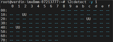
Now that the display is good, the touch chip configures the i2c pass-through mode via the 941 register, the address has been found and the touch drive can be loaded normally. 
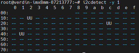
The register configuration for touch i2c transparent and interrupt transparent is as follows: 

# i2c pass-through

i2cset -y -f 1 0x12 0x03 0x9a

# SlaveID_0

i2cset -y -f 1 0x12 0x07 0x82

# SlaveAlias_0

i2cset -y -f 1 0x12 0x08 0x82

# Enable port0 REM_INTB

i2cset -y -f 1 0x12 0x30 0x01

The interrupt pin of the touch IC is connected to the INTB pin of the 928 and the corresponding REM_INTB pin of the 941 is connected to the GPIO port of the SoM. With a touch of the screen, the SoM interrupt GPIO is recognized as normal.

However, when click the screen multiple times, the driver reads the information reported by the touch IC via i2c. Some clicks correctly recognize the coordinate points and respond to touch events, but some clicks check for checksum errors. coordinate information is not recognized correctly.

It appears that the transmission data is prone to errors due to the i2c's unstable transmission signal through transmission. With the same touch IC, communication is generally good when previously connected directly to the i2c of the som. You can read the coordinates and respond with a few checksum errors.

1) Could you help give some recommendations? Is it required to adjust 941 and 928 specific register configurations to improve i2c transfers?

2) I2c settings for som to 941 are 400kHz, does the i2c rate for 928 transmissive need to be set separately to match the previous?

Could you help check this case? Thanks.

Best Regards,

Cherry

  • Part Number: DS90UB941AS-Q1

    A simplified application diagram is as follows: 

    941 addr = 0x12

    928 addr = 0x2c

    touch addr = 0x41

    The display can work normally. Now we config the register in 941 to enable i2c pass throgh, touch address can be found and touch driver can be loaded normally.

    Register configurations of touch slave device are as follows:

    # i2c pass-through

    i2cset -y -f 1 0x12 0x03 0x9a

    # SlaveID_0

    i2cset -y -f 1 0x12 0x07 0x82

    # SlaveAlias_0

    i2cset -y -f 1 0x12 0x08 0x82

    # Enable port0 REM_INTB

    i2cset -y -f 1 0x12 0x30 0x01

    touch IC interrupt pin is connected to INTB in 928, REM_INTB pin is connected to GPIO in SoM. When we touch the screen, GPIO can be detected normally by SoM.

    ----------------------------

    We click the screen by finger for serveral times, the driver will read messages transfered from touch IC, but only part of our click can be recognized and respond to click events. Checksum error detected for other clicks, can not be resolved into touch positions.

    It seems the i2c communication between 941<->928 <->touch IC  are not stable or incorrect. Because we connect the same touch IC to i2c bus in SoM directly,   touch IC works normally and rarely checksum errors occur.

    Q1:  Do you have some experience  to fix this problem? Maybe need to config some additional registers or other ways?

    Q2:  The speed between SoM and 941 is set to 400khz (fast mode) and do we need to set i2c speed between 928 and slave device and how to set?

    Thanks!

  • Hi, thanks for your question. Since the same question is posted by TI FAE (Cherry), we are going to consolidate threads for most effective communication. Feel free to follow-up with more information here. 

    Thanks, 

    Logan

  • Hi Cherry, 

    Since we are not sure where exactly the I2C failures are stemmed from and the nature of the error, we would like to see if the customer can set up logic analyzers at the host and the sink. Looking at the transactions can help us determine if there is a lock on the I2C bus, or some inaccurate transmissions. Also can you get the customer to share a register dump of the 941 and 948? 

    Best,

    Shu

  • Hi Logan and Shu,

    Thank you for the support!

    Would like to have the end customer  to give more details on the issue since he raised the ticket on E2ECHINA, please let me know if any questions.

    Hi ,

    Could you please help provide the information as Shu requested above? 

    Thanks and regards,

    Cherry

  • dump 941:

    dump 928:

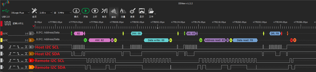
    Since touch data is too much for one click,so we use i2c-tools to get value of  register  0x00 from touch chip to test i2c communication, the command is " i2cget -f -y 1 0x41 0x00 ",

    and at the same time use logic analyzers to catch the process: 

  • Hello,

    Shu is OoO today and will be back tomorrow.

  • Hi Cherry and RM, 

    Thank you for the update. I will look into the configurations and do some testing to verify. Will update by the end of the week 10/27. 

    Best,

    Shu

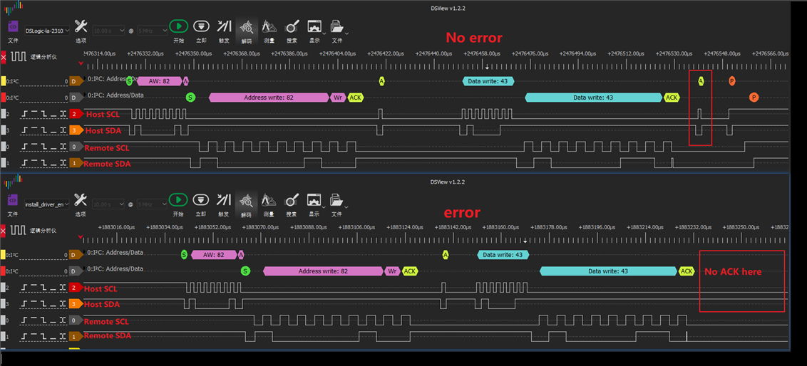
  • We also do some test and make a comparison with a logic analyzer, give some more information to you. We hope this could be helpful.

    In the picture, we test the i2c communication twice(Two operations are the same), one is ok and another has an error。

    You can see clearly that remote slave device(touch chip) send a ACK but there is no ACK in host side, then it leads to communication error in i2c driver and that cause the error -110  in previous replies。

  • Hi RM, 

    Thank you for the updated test. This looks like the I2C packets are being dropped due to poor back channel margins. From the 941 reg dump, registers 0xA and 0xB are reporting maxed CRC errors. Would you be able to clear the CRC error registers with the below CRC_ERROR_RESET to see how fast the errors are aggregating?

    Also some additional questions if you can help provide:

    1. How many systems are seeing this issue? 

    2. Have the systems been checked against the Return Loss/Insertion Loss thresholds in the FPD3 channel specs?

    3. What is the failure rate when attempting back channel I2C transactions 

    Would you be able to share the schematics and layout for me to cross check the FPD datapath? 

    Best,

    Shu

  • Hi Shu

    I did the test as you said:

    Firstly, execute "i2cset -f -y 1 0x12 0x04 0x20" to clear CRC errors.

    Next,  read 0x0a and 0x0b to make sure errors have been cleared.

    Then, execute "i2cset -f -y 1 0x12 0x04 0x00" to let counters to start working properly and at the same time start timing.

    Finally, it took about 2minutes and 15 seconds for the registers to arrive maximum value 0xFFFF from 0x0000.

    1. How many systems are seeing this issue? 

    R: Actually we only have two system now and the issues on two systems are similar.

    2. Have the systems been checked against the Return Loss/Insertion Loss thresholds in the FPD3 channel specs?

    R: Currently we haven't checked this.

    3. What is the failure rate when attempting back channel I2C transactions 

    R: We think about 30% but not exactly. For example, when we test 10 times, possible 3 times for i2c communication errors occurred.


  • Hi RM, 

    The aggregation of errors in the ~2 minute timeframe is indicating a poor back channel margin and we need to look at the channel specs/Signal integrity of the FPD path. 

    I also noticed on the 941 schematic that the AC coupling caps on DOUT- is out of spec for differential pair signal. Would you be able to provide some more information about the interconnect? I only see a Header on the SER schematic for the FPD signal. What are the connectors and cables being used? 

    I will share some information with over email about our channel spec requirements and how to measure. The documents are under NDA therefore, I cannot share on this public forum. 

    Best,

    Shu

  • Hi Shu,

    Thank you for the sharing and the info you shared has been forwarded to RM via email.

    Hi Rm,

    Please check the email and feel free to give some updates.

    Thanks and regards,

    Cherry

  • Hi Shu

    Yes, we We didn't notice the problem and today we change C1 C2 C3 C4 all to 100uF,and with this change, it tooks about 5 min for the registers to arrive maximum value,  it seems errors are growing a little slower.

    And then about cables, in fact the cable we used is not a standard twisted pair, and today we asked hardware engineer to make a standard twisted pair and do test.

    If any further news ,we will update to you.

  • Hi RM,

    Thank you for the update. I received update from the team in email that the STP cable is showing improvements and will undergo further testing. 

    Best,

    Shu

  • Yes, with the STP cable,  error "-110" disappeared during i2c communication and improvement is obvious.

    Then our hardware engineer will read the documents you send over email and do more test and improvements.

    Thanks.

  • Hi RM, 

    Sounds like good news. I will go ahead and close this thread. If there are additional support needed, please feel free to open another thread on E2E. 

    Best,

    Shu