


Part Number: DP83822I
Dear Specialists,
My customer is evaluating DP83822I and has a question.
I would be grateful if you could advise.
---
I created a circuit by connecting an LED to the LED_1/GPIO1 terminal.
+3.3V is connected to the anode of the LED, the cathode is connected to a 1kΩ resistorI(RCL), and the other end of the resistor is connected to the LED_1/GPIO1 terminal.
Since the VF of the LED is about 1.9V, it is calculated that about 1.5mA will flow.
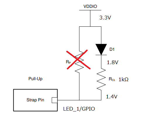
At this time, when the DP83822IRHBR reset (+3.3V is supplied), this LED will light up weakly.
The voltage across the resistor is about 0.4V, and 0.4mA flows through the LED, making it dim.
It seems to be lighting up steadily (the cathode side of the LED was 1.8V and the LED_1/GPIO1 terminal side was 1.4V).
Could you please answer questions below.
①About circuit operation
Could you please tell me the circuit operation that causes the LED to dimly light?
P.7 Table6-1 The LED_1/GPIO1 pin is marked as internal pull-down (S-PD).
On the other hand, the datasheet LED_1/GPIO1 states that it is tri-stated by default.
Which one is correct?
②About the problem
Are there any problems with connection ?
The data sheet says to connect a resistor in parallel.
I wonder if the LED is weakly lit because there is no parallel resistor?
③ pull-up/pull-down values of LED_1/GPIO pin
According to actual measurements, the voltage across RCL is 1.8V/1.4V, and 0.4mA flows.
The internal resistance value of the IC is calculated 1.4V/0.4mA=3.5kΩ. Is it correct?
I would like to know the typical value and deviation %.
---
I appreciate your great help in advance.
Best regards,
Shinichi
