This thread has been locked.

If you have a related question, please click the "Ask a related question" button in the top right corner. The newly created question will be automatically linked to this question.

SN65DSI86: Application issues of chips

Part Number: SN65DSI86
Other Parts Discussed in Thread: TEST2

Our project uses SN65DSI86 mipi to eDP, but now there is only backlight, no image, and no color bar display. What needs to be checked? Help guide and see where there may be problems.

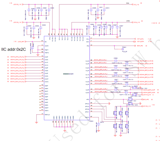
Below are software and schematic diagrams to help check if they are correct.

sn65dsi86_init_1th.txt
VOID sn65dsi86_regInit(VOID)
{
    sn65dsi86_write(SW_RST,     0x00);
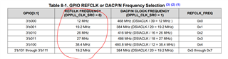
    sn65dsi86_write(CLK_REG_0A, 0x03);// REFCLK_FREQ/DPPLL_CLK_SRC
    sn65dsi86_write(CLK_REG_0D, 0x00);//songer
    sn65dsi86_write(DSI_REG_10, 0x26);//songer
    sn65dsi86_write(DSI_REG_11, 0x00);//songer
    sn65dsi86_write(DSI_REG_12, 0x4c);//songer  --------..note  CHA_DSI_CLK_RANGE  0x50 400 < 405
    sn65dsi86_write(DSI_REG_13, 0x4c); //chanel B

    sn65dsi86_write(VIDEO_REG_20, 0x80);//songer,the length in pixels of the active horizontal line for Channel A
    sn65dsi86_write(VIDEO_REG_21, 0x07);//songer,the length in pixels of the active horizontal line for Channel A
    sn65dsi86_write(VIDEO_REG_22, 0x00); //chanel B
    sn65dsi86_write(VIDEO_REG_23, 0x00); //Chanel B
    sn65dsi86_write(VIDEO_REG_24, 0x38);// the vertical display size in lines for Channel A
    sn65dsi86_write(VIDEO_REG_25, 0x04);// the vertical display size in lines for Channel A

    sn65dsi86_write(VIDEO_REG_2C, 0x13);// CHA_HSYNC_PULSE_WIDTH_LOW -------...note
    sn65dsi86_write(VIDEO_REG_2D, 0x00);// CHA_HSYNC_POLARITY/CHA_HSYNC_PULSE_WIDTH_HIGH ------...note
    sn65dsi86_write(VIDEO_REG_30, 0x08);// CHA_VSYNC_PULSE_WIDTH_LOW  -----..note
    sn65dsi86_write(VIDEO_REG_31, 0x00);//CHA_VSYNC_POLARITY/CHA_VSYNC_PULSE_WIDTH_HIGH ----...note

    sn65dsi86_write(VIDEO_REG_34, 0x14);//CHA_HORIZONTAL_BACK_PORCH
    sn65dsi86_write(VIDEO_REG_36, 0x0b);//CHA_VERTICAL_BACK_PORCH
    sn65dsi86_write(VIDEO_REG_38, 0x1e);//CHA_HORIZONTAL_FRONT_PORCH
    sn65dsi86_write(VIDEO_REG_3A, 0x0c);//CHA_VERTICAL_FRONT_PORCH

    sn65dsi86_write(VIDEO_REG_3C, 0x10); // songer COLOR_BAR_EN-->1
    sn65dsi86_write(VIDEO_REG_3D, 0x00); // songer
    sn65dsi86_write(VIDEO_REG_3E, 0x00); // songer

    sn65dsi86_write(DP_SPEC_REG_5B, 0x00); // songer
    sn65dsi86_write(LK_TRAIN_REG_93, 0x34);//songer
    sn65dsi86_write(LK_TRAIN_REG_94, 0xe0);//songer

    sn65dsi86_write(DP_SPEC_REG_5C, 0x01); // songer
    sn65dsi86_write(DP_SPEC_REG_5A, 0x05);// default 0x05, IDLE pattern enable

    sn65dsi86_write(CLK_REG_0D, 0x01);//songer pll_enable
    MDP_OSAL_DELAYMS(10);
    sn65dsi86_DebugDumpReg(CLK_REG_0D);

    sn65dsi86_write(I2C_OVER_AUX_REG_64, 0x01);
    sn65dsi86_write(I2C_OVER_AUX_REG_74, 0x00);
    sn65dsi86_write(I2C_OVER_AUX_REG_75, 0x01);
    sn65dsi86_write(I2C_OVER_AUX_REG_76, 0x0A);
    sn65dsi86_write(I2C_OVER_AUX_REG_77, 0x01);
    sn65dsi86_write(I2C_OVER_AUX_REG_78, 0x81);
    MDP_OSAL_DELAYMS(10);

    sn65dsi86_write(LK_TRAIN_REG_96, 0x0a);// 01 --> 0a
    MDP_OSAL_DELAYMS(20);

    sn65dsi86_write(DP_SPEC_REG_5A, 0x05);//songer temp
}

  • Hey Tony, 

    Schematic reviews tend to take some time. Ill have one ready by the end of the week. While I'm working on that please have a look at the following FAQ to help the debug process. 

    https://e2e.ti.com/support/interface-group/interface/f/interface-forum/945403/faq-sn65dsi86-sn65dsi86-black-screen-debugging-guide?tisearch=e2e-sitesearch&keymatch=sn65dsi86#

    https://e2e.ti.com/support/interface-group/interface/f/interface-forum/1268829/faq-sn65dsi86-sn65dsi86-resolution-guide?tisearch=e2e-sitesearch&keymatch=sn65dsi86#

    Most likely this is a timing issue coming from the DSI side. The biggest factors to consider are making sure the horizontal and vertical front porch(FP), back porch(BP), and sync pulse(SP) are all lined up on the input and output side. It looks like you are using the REFCLK, so make sure the frequency of REFCLK is within spec for the sink. 

    Try using this script to see if you can get the internal color bar display to show. If this script works, then the issue is on the DSI side not the output side. 

    1488.1DP_4DSI_HBR_800x600_Color_Bar.xml
    <aardvark>
        <configure i2c="1" spi="1" gpio="0" tpower="1" pullups="1"/>
        <i2c_bitrate khz="100"/>
        
      <i2c_write addr="0x2D" count="1" radix="16">5C 01</i2c_write> <sleep ms="10"/>
    
       <i2c_write addr="0x2D" count="1" radix="16">FF 07</i2c_write> <sleep ms="10"/>
    
    ======DUMP CFR======
       <i2c_write addr="0x2D" count="0" radix="16">16 </i2c_write> <sleep ms="10"/>
    
    ======Read======
        <i2c_read addr="0x2D" count="1" radix="16">00</i2c_read> <sleep ms="10"/>
    
    
       <i2c_write addr="0x2D" count="1" radix="16">16 01</i2c_write> <sleep ms="10"/>
    
       <i2c_write addr="0x2D" count="0" radix="16">16 </i2c_write> <sleep ms="10"/>
    
    ======Read======
        <i2c_read addr="0x2D" count="2" radix="16">00</i2c_read> <sleep ms="10"/>
    
      <i2c_write addr="0x2D" count="1" radix="16">FF 00</i2c_write> <sleep ms="10"/>
    
    
    ======Single 4 DSI lanes======
    
      <i2c_write addr="0x2D" count="1" radix="16">10 26 </i2c_write> <sleep ms="10"/>
    
    ======DSI CLK FREQ======
    
      <i2c_write addr="0x2D" count="0" radix="16">12 </i2c_write> <sleep ms="10"/>
       <i2c_read addr="0x2D" count="2" radix="16">00</i2c_read> <sleep ms="10"/>


    ======enhanced framing======
    
      <i2c_write addr="0x2D" count="1" radix="16">5A 04 </i2c_write> <sleep ms="10"/>
    
    
    ======ADDR 0x93 CFR======
    
       <i2c_write addr="0x2D" count="0" radix="16">93</i2c_write> <sleep ms="10"/>
    
    ======Read======
        <i2c_read addr="0x2D" count="6" radix="16">00</i2c_read> <sleep ms="10"/>
    
    ======Pre0dB 1 lanes no SSC======
       <i2c_write addr="0x2D" count="1" radix="16">93 10</i2c_write> <sleep ms="10"/>
    
    ======L0mV RBR======
       <i2c_write addr="0x2D" count="1" radix="16">94 80</i2c_write> <sleep ms="10"/>
    
    ======POST2 0dB ======
       <i2c_write addr="0x2D" count="1" radix="16">95 00</i2c_write> <sleep ms="10"/>
    
    ======PLL ENABLE======
       <i2c_write addr="0x2D" count="1" radix="16">0D 01</i2c_write> <sleep ms="10"/>
       <i2c_write addr="0x2D" count="0" radix="16">0A</i2c_write> <sleep ms="10"/>
       <i2c_read addr="0x2D" count="2" radix="16">00</i2c_read> <sleep ms="10"/>


    ======Semi-Auto TRAIN ======
       <i2c_write addr="0x2D" count="1" radix="16">96 0A</i2c_write> <sleep ms="20"/>
    
    
    ======ADDR 0x0A CFR======
    
       <i2c_write addr="0x2D" count="0" radix="16">96</i2c_write> <sleep ms="20"/>
    
    ======Read======
        <i2c_read addr="0x2D" count="1" radix="16">00</i2c_read> <sleep ms="10"/>
    
    =====CHA_ACTIVE_LINE_LENGTH=======
        <i2c_write addr="0x2D" count="2" radix="16">20 00 04</i2c_write> <sleep ms="10"/>
    
    =====CHA_VERTICAL_DISPLAY_SIZE=======
        <i2c_write addr="0x2D" count="2" radix="16">24 58 02</i2c_write> <sleep ms="10"/>
    
    =====CHA_SYNC_DELAY=======
        <i2c_write addr="0x2D" count="2" radix="16">28 00 00</i2c_write> <sleep ms="10"/>
    
    =====CHA_HSYNC_PULSE_WIDTH=======
        <i2c_write addr="0x2D" count="2" radix="16">2C 80 80</i2c_write> <sleep ms="10"/>
    
    =====CHA_VSYNC_PULSE_WIDTH=======
        <i2c_write addr="0x2D" count="2" radix="16">30 04 80</i2c_write> <sleep ms="10"/>
    
    =====CHA_HORIZONTAL_BACK_PORCH=======
        <i2c_write addr="0x2D" count="1" radix="16">34 28 </i2c_write> <sleep ms="10"/>
    
    =====CHA_VERTICAL_BACK_PORCH=======
        <i2c_write addr="0x2D" count="1" radix="16">36 09</i2c_write> <sleep ms="10"/>
    
    =====CHA_HORIZONTAL_FRONT_PORCH=======
        <i2c_write addr="0x2D" count="1" radix="16">38 28</i2c_write> <sleep ms="10"/>
    
    =====CHA_VERTICAL_FRONT_PORCH=======
        <i2c_write addr="0x2D" count="1" radix="16">3A 01</i2c_write> <sleep ms="10"/>
    
    =====DP_18BPP_EN =======
      <i2c_write addr="0x2D" count="1" radix="16">5B 01 </i2c_write> <sleep ms="100"/>
    
    =====COLOR BAR =======
        <i2c_write addr="0x2D" count="1" radix="16">3C 10</i2c_write> <sleep ms="100"/>
    
    ======enhanced framing and Vstream enable======
    
      <i2c_write addr="0x2D" count="1" radix="16">5A 0C </i2c_write> <sleep ms="100"/>
    
    ======DUMP CFR======
        <i2c_write addr="0x2D" count="0" radix="16">20</i2c_write> <sleep ms="10"/>
    
    ======Read======
        <i2c_read addr="0x2D" count="32" radix="16">00</i2c_read> <sleep ms="10"/>


    </aardvark>
    

  • Currently, our screen is not working properly. Can you help us troubleshoot the issue or provide some guidance on the adapter chip? SN65DSI86ZQER mipi to eDP, enable color bar edp panel without display, only backlight.

    1. Can the REFCLK of the IC be grounded, and the clk of the mipi only be one of 384MHz, 416MHz, 460.8MHz, 468MHz, or 486MHz?

    2. If the color bar is enabled, does the mipi's video timing also need to be consistent with the panel's?

    3. There are dump f0~f8 registers, 0xf1=0x03 0xf4=0x01 0xf8=0x01, to help analyze the situation that may cause these flag positions 1

    4. If ASSR is closed, does test2 need to be pulled up?

    SN65DSI86ZQER_mipiToEdp_1026.txt
    -----------------------------init code-------------------------------------------
    VOID sn65dsi86_regInit(VOID)
    {
        // uint8 temp;
        sn65dsi86_write(SW_RST,     0x01);
        MDP_OSAL_DELAYMS(10);
    
        // sn65dsi86_write(0xff, 0x07);
        // sn65dsi86_read(0x16, &temp);
        // SN65DSI86ZQER_DEBUG_INFO_1("SN65DSI86ZQER: ---- temp:%d\n",temp);
        // sn65dsi86_write(0x16, 0x01);
        // sn65dsi86_read(0x16, &temp);
        // SN65DSI86ZQER_DEBUG_INFO_1("SN65DSI86ZQER: temp:%d\n",temp);
        // sn65dsi86_write(0xff, 0x00);
        // sn65dsi86_write(0xf4, 0xff);
    
        sn65dsi86_write(CLK_REG_0A, 0x09);// REFCLK_FREQ/DPPLL_CLK_SRC
        sn65dsi86_write(CLK_REG_0D, 0x00);//songer
        sn65dsi86_write(DSI_REG_10, 0x26);//songer
        sn65dsi86_write(DSI_REG_11, 0x00);//songer
        sn65dsi86_write(DSI_REG_12, 0x5c);//songer  --------..note  CHA_DSI_CLK_RANGE  0x50 400 < 405
        sn65dsi86_write(DSI_REG_13, 0x5c); //chanel B
    
        sn65dsi86_write(VIDEO_REG_20, 0x80);//songer,the length in pixels of the active horizontal line for Channel A
        sn65dsi86_write(VIDEO_REG_21, 0x07);//songer,the length in pixels of the active horizontal line for Channel A
        sn65dsi86_write(VIDEO_REG_22, 0x00); //chanel B
        sn65dsi86_write(VIDEO_REG_23, 0x00); //Chanel B
        sn65dsi86_write(VIDEO_REG_24, 0x38);// the vertical display size in lines for Channel A
        sn65dsi86_write(VIDEO_REG_25, 0x04);// the vertical display size in lines for Channel A
    
        sn65dsi86_write(VIDEO_REG_2C, 0x38);// CHA_HSYNC_PULSE_WIDTH_LOW -------...note
        sn65dsi86_write(VIDEO_REG_2D, 0x80);// CHA_HSYNC_POLARITY/CHA_HSYNC_PULSE_WIDTH_HIGH ------...note
        sn65dsi86_write(VIDEO_REG_30, 0x0a);// CHA_VSYNC_PULSE_WIDTH_LOW  -----..note
        sn65dsi86_write(VIDEO_REG_31, 0x80);//CHA_VSYNC_POLARITY/CHA_VSYNC_PULSE_WIDTH_HIGH ----...note
    
        sn65dsi86_write(VIDEO_REG_34, 0x70);//CHA_HORIZONTAL_BACK_PORCH
        sn65dsi86_write(VIDEO_REG_36, 0x12);//CHA_VERTICAL_BACK_PORCH
        sn65dsi86_write(VIDEO_REG_38, 0x70);//CHA_HORIZONTAL_FRONT_PORCH
        sn65dsi86_write(VIDEO_REG_3A, 0x11);//CHA_VERTICAL_FRONT_PORCH
    
        sn65dsi86_write(VIDEO_REG_3C, 0x17); // songer COLOR_BAR_EN-->1   // Vertical Colors: Stripes
        sn65dsi86_write(VIDEO_REG_3D, 0x00); // songer
        sn65dsi86_write(VIDEO_REG_3E, 0x00); // songer
    
        sn65dsi86_write(DP_SPEC_REG_5B, 0x00); // songer
        sn65dsi86_write(LK_TRAIN_REG_93, 0x34);//songer
        sn65dsi86_write(LK_TRAIN_REG_94, 0xe0);//songer
    
        sn65dsi86_write(DP_SPEC_REG_5C, 0x01); // songer
        sn65dsi86_write(DP_SPEC_REG_5A, 0x05);// default 0x05, IDLE pattern enable
    
        sn65dsi86_write(CLK_REG_0D, 0x01);//songer pll_enable
        MDP_OSAL_DELAYMS(10);
        sn65dsi86_DebugDumpReg(CLK_REG_0D);
    
        sn65dsi86_write(I2C_OVER_AUX_REG_64, 0x01);
        sn65dsi86_write(I2C_OVER_AUX_REG_74, 0x00);
        sn65dsi86_write(I2C_OVER_AUX_REG_75, 0x01);
        sn65dsi86_write(I2C_OVER_AUX_REG_76, 0x0A);
        sn65dsi86_write(I2C_OVER_AUX_REG_77, 0x01);
        sn65dsi86_write(I2C_OVER_AUX_REG_78, 0x81);
        MDP_OSAL_DELAYMS(10);
    
        sn65dsi86_write(LK_TRAIN_REG_96, 0x0a);// 01 --> 0a
        MDP_OSAL_DELAYMS(20);
    
        sn65dsi86_write(DP_SPEC_REG_5A, 0x05);//songer temp
    }
    
    -------------------------------------------------------------------------------------------------------------
    sn65dsi86: power up success 2th!!
    SN65DSI86ZQER: read device id match result:success
    SN65DSI86ZQER: read status:Success       regAddr:0x0D,  regValue:0x01
    SN65DSI86ZQER: read status:Success       regAddr:0x0A,  regValue:0x89
    SN65DSI86ZQER: read status:Success       regAddr:0x0D,  regValue:0x01
    SN65DSI86ZQER: read status:Success       regAddr:0x10,  regValue:0x26
    SN65DSI86ZQER: read status:Success       regAddr:0x11,  regValue:0x00
    SN65DSI86ZQER: read status:Success       regAddr:0x12,  regValue:0x5C
    SN65DSI86ZQER: read status:Success       regAddr:0x13,  regValue:0x5C
    SN65DSI86ZQER: read status:Success       regAddr:0x20,  regValue:0x80
    SN65DSI86ZQER: read status:Success       regAddr:0x21,  regValue:0x07
    SN65DSI86ZQER: read status:Success       regAddr:0x22,  regValue:0x00
    SN65DSI86ZQER: read status:Success       regAddr:0x23,  regValue:0x00
    SN65DSI86ZQER: read status:Success       regAddr:0x24,  regValue:0x38
    SN65DSI86ZQER: read status:Success       regAddr:0x25,  regValue:0x04
    SN65DSI86ZQER: read status:Success       regAddr:0x2C,  regValue:0x38
    SN65DSI86ZQER: read status:Success       regAddr:0x2D,  regValue:0x80
    SN65DSI86ZQER: read status:Success       regAddr:0x30,  regValue:0x0A
    SN65DSI86ZQER: read status:Success       regAddr:0x31,  regValue:0x80
    SN65DSI86ZQER: read status:Success       regAddr:0x34,  regValue:0x70
    SN65DSI86ZQER: read status:Success       regAddr:0x36,  regValue:0x12
    SN65DSI86ZQER: read status:Success       regAddr:0x38,  regValue:0x70
    SN65DSI86ZQER: read status:Success       regAddr:0x3A,  regValue:0x11
    SN65DSI86ZQER: read status:Success       regAddr:0x3C,  regValue:0x17
    SN65DSI86ZQER: read status:Success       regAddr:0x3D,  regValue:0x00
    SN65DSI86ZQER: read status:Success       regAddr:0x3E,  regValue:0x00
    SN65DSI86ZQER: read status:Success       regAddr:0x5A,  regValue:0x05
    SN65DSI86ZQER: read status:Success       regAddr:0x5B,  regValue:0x00
    SN65DSI86ZQER: read status:Success       regAddr:0x5C,  regValue:0x11
    SN65DSI86ZQER: read status:Success       regAddr:0x93,  regValue:0x74
    SN65DSI86ZQER: read status:Success       regAddr:0x94,  regValue:0xE0
    SN65DSI86ZQER: read status:Success       regAddr:0x96,  regValue:0x01
    sn65dsi86: dump irq status register start ------------------
    SN65DSI86ZQER: read status:Success       regAddr:0xF0,  regValue:0x00
    SN65DSI86ZQER: read status:Success       regAddr:0xF1,  regValue:0x03
    SN65DSI86ZQER: read status:Success       regAddr:0xF2,  regValue:0x00
    SN65DSI86ZQER: read status:Success       regAddr:0xF3,  regValue:0x00
    SN65DSI86ZQER: read status:Success       regAddr:0xF4,  regValue:0x01
    SN65DSI86ZQER: read status:Success       regAddr:0xF5,  regValue:0x00
    SN65DSI86ZQER: read status:Success       regAddr:0xF6,  regValue:0x00
    SN65DSI86ZQER: read status:Success       regAddr:0xF7,  regValue:0x00
    SN65DSI86ZQER: read status:Success       regAddr:0xF8,  regValue:0x01
    

  • 1) I suggest using REFCLK rather than grounding it. This will give a cleaner clock and cleaner output. 

    2) If the color bar is enables you are only using the output side of the chip. This means that MIPI signal is not a factor.

    3) Details on the meaning of the error registers can be found in section 8.6 under table 8-31.

    4) Pulling TEST2 up will make the ASSR_CONTROL register R/W instead of R. This may help. 

    I suggest using all the different REFCLK frequencies to see if one works. 

  • May I help you take a look again

    1. Enable the color bar to display normally, but after turning off the color bar, the screen does not display. What should be the problem?

    2. Read the EDID according to Datasheet 8.4.5.3.2, and all readings are 0x00. Can you help check if the logic for reading the EDID is correct? If not, what should be correct?

    initCode.c
    VOID sn65dsi86_ReadEDID(VOID)
    {
        /*  0x74    AUX_ADDR[19:16]:
            0x75    AUX_ADDR[15:8]
            0x76    AUX_ADDR[7:0].
            0x77    AUX_LENGTH
    
            0x64    AUX_WDATA0
            ....
            0x73    AUX_WDATA15
    
            0x78    AUX_CMD/SEND
         */
        uint16 i;
        uint8 aux_data = 0;
        uint8 temp = 0;
        sn65dsi86_write(0xf4, 0xff);
    
        //step1
        sn65dsi86_write(I2C_OVER_AUX_REG_74, 0x00);
        sn65dsi86_write(I2C_OVER_AUX_REG_75, 0x00);
        sn65dsi86_write(I2C_OVER_AUX_REG_76, 0x50);
        sn65dsi86_write(I2C_OVER_AUX_REG_77, 0x00);
        sn65dsi86_write(I2C_OVER_AUX_REG_78, 0x41);
        MDP_OSAL_DELAYMS(30);
        SN65DSI86ZQER_DEBUG_INFO_1("SN65DSI86ZQER: --------------------step1----------------\n");
        sn65dsi86_DebugIrqStatusReg();
    
        //step5
        sn65dsi86_write(I2C_OVER_AUX_REG_64, 0x00);
        sn65dsi86_write(I2C_OVER_AUX_REG_74, 0x00);
        sn65dsi86_write(I2C_OVER_AUX_REG_75, 0x00);
        sn65dsi86_write(I2C_OVER_AUX_REG_76, 0x50);
        sn65dsi86_write(I2C_OVER_AUX_REG_77, 0x01);
        sn65dsi86_write(I2C_OVER_AUX_REG_78, 0x41);
        sn65dsi86_write(0xf4, 0xff);
        MDP_OSAL_DELAYMS(30);
        SN65DSI86ZQER_DEBUG_INFO_1("SN65DSI86ZQER: ----------------------step5--------------\n");
        sn65dsi86_DebugIrqStatusReg();
    
        //step9
        sn65dsi86_write(I2C_OVER_AUX_REG_74, 0x00);
        sn65dsi86_write(I2C_OVER_AUX_REG_75, 0x00);
        sn65dsi86_write(I2C_OVER_AUX_REG_76, 0x50);
        sn65dsi86_write(I2C_OVER_AUX_REG_77, 0x00);
        sn65dsi86_write(I2C_OVER_AUX_REG_78, 0x51);
        sn65dsi86_write(0xf4, 0xff);
        MDP_OSAL_DELAYMS(30);
        SN65DSI86ZQER_DEBUG_INFO_1("SN65DSI86ZQER: ----------------------step9--------------\n");
        sn65dsi86_DebugIrqStatusReg();
    
    
        //step13
        sn65dsi86_write(I2C_OVER_AUX_REG_74, 0x00);
        sn65dsi86_write(I2C_OVER_AUX_REG_75, 0x00);
        sn65dsi86_write(I2C_OVER_AUX_REG_76, 0x50);
        sn65dsi86_write(I2C_OVER_AUX_REG_77, 0x10);
        sn65dsi86_write(I2C_OVER_AUX_REG_78, 0x51);
        SN65DSI86ZQER_DEBUG_INFO_1("SN65DSI86ZQER: ----------------------step13--------------\n");
        MDP_OSAL_DELAYMS(30);
    
        SN65DSI86ZQER_DEBUG_INFO_1("SN65DSI86ZQER: ----------------------read result  1--------------\n");
        for(i=0x64; i<=0x73; i++){
            sn65dsi86_read(i, &aux_data);
            SN65DSI86ZQER_DEBUG_INFO_1("SN65DSI86ZQER: reg:0x%02x\tAUX_DATA[%d]:0x%02x\n",i,temp,aux_data);
            temp++;
        }
    
        //step13
        sn65dsi86_write(I2C_OVER_AUX_REG_74, 0x00);
        sn65dsi86_write(I2C_OVER_AUX_REG_75, 0x00);
        sn65dsi86_write(I2C_OVER_AUX_REG_76, 0x50);
        sn65dsi86_write(I2C_OVER_AUX_REG_77, 0x10);
        sn65dsi86_write(I2C_OVER_AUX_REG_78, 0x51);
        SN65DSI86ZQER_DEBUG_INFO_1("SN65DSI86ZQER: ----------------------step13--------------\n");
        MDP_OSAL_DELAYMS(30);
        SN65DSI86ZQER_DEBUG_INFO_1("SN65DSI86ZQER: ----------------------read result  2--------------\n");
        for(i=0x64; i<=0x73; i++){
            sn65dsi86_read(i, &aux_data);
            SN65DSI86ZQER_DEBUG_INFO_1("SN65DSI86ZQER: reg:0x%02x\tAUX_DATA[%d]:0x%02x\n",i,temp,aux_data);
            temp++;
        }
    
        //step13
        sn65dsi86_write(I2C_OVER_AUX_REG_74, 0x00);
        sn65dsi86_write(I2C_OVER_AUX_REG_75, 0x00);
        sn65dsi86_write(I2C_OVER_AUX_REG_76, 0x50);
        sn65dsi86_write(I2C_OVER_AUX_REG_77, 0x10);
        sn65dsi86_write(I2C_OVER_AUX_REG_78, 0x51);
        SN65DSI86ZQER_DEBUG_INFO_1("SN65DSI86ZQER: ----------------------step13--------------\n");
        MDP_OSAL_DELAYMS(30);
        SN65DSI86ZQER_DEBUG_INFO_1("SN65DSI86ZQER: ----------------------read result  3--------------\n");
        for(i=0x64; i<=0x73; i++){
            sn65dsi86_read(i, &aux_data);
            SN65DSI86ZQER_DEBUG_INFO_1("SN65DSI86ZQER: reg:0x%02x\tAUX_DATA[%d]:0x%02x\n",i,temp,aux_data);
            temp++;
        }
    
        MDP_OSAL_DELAYMS(10);
        sn65dsi86_write(I2C_OVER_AUX_REG_74, 0x00);
        sn65dsi86_write(I2C_OVER_AUX_REG_75, 0x00);
        sn65dsi86_write(I2C_OVER_AUX_REG_76, 0x50);
        sn65dsi86_write(I2C_OVER_AUX_REG_77, 0x00);
        sn65dsi86_write(I2C_OVER_AUX_REG_78, 0x11);
    
    }
    
    VOID sn65dsi86_regInit(VOID)
    {
        // uint8 temp;
        sn65dsi86_write(SW_RST,     0x01);
        MDP_OSAL_DELAYMS(10);
    
        // sn65dsi86_write(0xff, 0x07);
        // sn65dsi86_read(0x16, &temp);
        // SN65DSI86ZQER_DEBUG_INFO_1("SN65DSI86ZQER: ---- temp:%d\n",temp);
        // sn65dsi86_write(0x16, 0x01);
        // sn65dsi86_read(0x16, &temp);
        // SN65DSI86ZQER_DEBUG_INFO_1("SN65DSI86ZQER: temp:%d\n",temp);
        // sn65dsi86_write(0xff, 0x00);
        // sn65dsi86_write(0xf4, 0xff);
    
        sn65dsi86_write(CLK_REG_0A,      0x05);// REFCLK_FREQ/DPPLL_CLK_SRC
        sn65dsi86_write(CLK_REG_0D,      0x00);//
        sn65dsi86_write(DSI_REG_10,      0x26);//
        sn65dsi86_write(DSI_REG_11,      0x00);//
        sn65dsi86_write(DSI_REG_12,      0x53);//  --------..note  CHA_DSI_CLK_RANGE  0x50 400 < 405
        sn65dsi86_write(DSI_REG_13,      0x53); //chanel B
        sn65dsi86_write(VIDEO_REG_20,    0x80);//,the length in pixels of the active horizontal line for Channel A
        sn65dsi86_write(VIDEO_REG_21,    0x07);//,the length in pixels of the active horizontal line for Channel A
        sn65dsi86_write(VIDEO_REG_22,    0x00); //chanel B
        sn65dsi86_write(VIDEO_REG_23,    0x00); //Chanel B
        sn65dsi86_write(VIDEO_REG_24,    0x38);// the vertical display size in lines for Channel A
        sn65dsi86_write(VIDEO_REG_25,    0x04);// the vertical display size in lines for Channel A
        sn65dsi86_write(VIDEO_REG_2C,    0x20);// CHA_HSYNC_PULSE_WIDTH_LOW -------...note
        sn65dsi86_write(VIDEO_REG_2D,    0x00);// CHA_HSYNC_POLARITY/CHA_HSYNC_PULSE_WIDTH_HIGH ------...note
        sn65dsi86_write(VIDEO_REG_30,    0x05);// CHA_VSYNC_PULSE_WIDTH_LOW  -----..note
        sn65dsi86_write(VIDEO_REG_31,    0x00);//CHA_VSYNC_POLARITY/CHA_VSYNC_PULSE_WIDTH_HIGH ----...note
        sn65dsi86_write(VIDEO_REG_34,    0x50);//CHA_HORIZONTAL_BACK_PORCH
        sn65dsi86_write(VIDEO_REG_36,    0x17);//CHA_VERTICAL_BACK_PORCH
        sn65dsi86_write(VIDEO_REG_38,    0x30);//CHA_HORIZONTAL_FRONT_PORCH
        sn65dsi86_write(VIDEO_REG_3A,    0x03);//CHA_VERTICAL_FRONT_PORCH
        sn65dsi86_write(VIDEO_REG_3C,    0x00); //  COLOR_BAR_EN-->1   // Vertical Colors: Stripes
        sn65dsi86_write(VIDEO_REG_3D,    0x00); // 
        sn65dsi86_write(VIDEO_REG_3E,    0x00); // 
        sn65dsi86_write(DP_SPEC_REG_5B,  0x00); // 
        sn65dsi86_write(LK_TRAIN_REG_93, 0x34);//
        sn65dsi86_write(LK_TRAIN_REG_94, 0xe0);//
    
    
        sn65dsi86_write(DP_SPEC_REG_5C,  0x01); // 
        sn65dsi86_write(DP_SPEC_REG_5A, 0x05);// default 0x05, IDLE pattern enable
    
        sn65dsi86_write(CLK_REG_0D, 0x01);//pll_enable
        MDP_OSAL_DELAYMS(10);
        sn65dsi86_DebugDumpReg(CLK_REG_0D);
    
        sn65dsi86_write(I2C_OVER_AUX_REG_64, 0x01);
        sn65dsi86_write(I2C_OVER_AUX_REG_74, 0x00);
        sn65dsi86_write(I2C_OVER_AUX_REG_75, 0x01);
        sn65dsi86_write(I2C_OVER_AUX_REG_76, 0x0A);
        sn65dsi86_write(I2C_OVER_AUX_REG_77, 0x01);
        sn65dsi86_write(I2C_OVER_AUX_REG_78, 0x81);
        MDP_OSAL_DELAYMS(10);
    
        sn65dsi86_write(LK_TRAIN_REG_96, 0x0a);// 01 --> 0a
        MDP_OSAL_DELAYMS(20);
    
        sn65dsi86_write(DP_SPEC_REG_5A, 0x0D);//temp
    }
    
    
    //dump reg f0~F8
    /*
    sn65dsi86: power up success 2th!!
    SN65DSI86ZQER: read device id match result:success
    SN65DSI86ZQER: read status:Success       regAddr:0x0D,  regValue:0x01
    sn65dsi86: dump irq status register start ------------------
    SN65DSI86ZQER: read status:Success       regAddr:0xF0,  regValue:0x00
    SN65DSI86ZQER: read status:Success       regAddr:0xF1,  regValue:0x00
    SN65DSI86ZQER: read status:Success       regAddr:0xF2,  regValue:0x00
    SN65DSI86ZQER: read status:Success       regAddr:0xF3,  regValue:0x00
    SN65DSI86ZQER: read status:Success       regAddr:0xF4,  regValue:0x01
    SN65DSI86ZQER: read status:Success       regAddr:0xF5,  regValue:0x00
    SN65DSI86ZQER: read status:Success       regAddr:0xF6,  regValue:0x00
    SN65DSI86ZQER: read status:Success       regAddr:0xF7,  regValue:0x00
    SN65DSI86ZQER: read status:Success       regAddr:0xF8,  regValue:0x01
    SN65DSI86ZQER: -----color bar status 0x3c:0x00
    */

  • Hey Tony,

    Here is the script I use to read the EDID. 

    EDID.xml
    <aardvark>
    <configure i2c="1" spi="1" gpio="0" tpower="1" pullups="1" />
    <i2c_bitrate khz="100" />
    
    ======Program AUX_CMD=0x4======
    <i2c_write addr="0x2D" count="1" radix="16">78 40</i2c_write> />
    <i2c_write addr="0x2D" count="1" radix="16">76 50</i2c_write> />
    <i2c_write addr="0x2D" count="1" radix="16">77 00</i2c_write> />
    ======Send======
    <i2c_write addr="0x2D" count="1" radix="16">78 41</i2c_write> />
    ======Make sure SEND_INT is set and no errors======
    <i2c_write addr="0x2D" count="0" radix="16">F4</i2c_write> />
    <i2c_read addr="0x2D" count="1" radix="16">00</i2c_read> />
    ======Clear 0xF4======
    <i2c_write addr="0x2D" count="0" radix="16">F4 FF</i2c_write> />
    ======Read to make sure 0xF4 is cleared ======
    <i2c_write addr="0x2D" count="0" radix="16">F4</i2c_write> />
    <i2c_read addr="0x2D" count="1" radix="16">00</i2c_read> />
    ======Read to make sure SEND bit is cleared======
    <i2c_write addr="0x2D" count="0" radix="16">78</i2c_write> />
    <i2c_read addr="0x2D" count="1" radix="16">00</i2c_read> />
    
    
    ======Program AUX_CMD=0x4======
    <i2c_write addr="0x2D" count="1" radix="16">78 40</i2c_write> />
    <i2c_write addr="0x2D" count="1" radix="16">76 50</i2c_write> />
    <i2c_write addr="0x2D" count="1" radix="16">77 01</i2c_write> />
    <i2c_write addr="0x2D" count="1" radix="16">64 00</i2c_write> />
    ======Send======
    <i2c_write addr="0x2D" count="1" radix="16">78 41</i2c_write> />
    ======Make sure SEND_INT is set and no errors======
    <i2c_write addr="0x2D" count="0" radix="16">F4</i2c_write> />
    <i2c_read addr="0x2D" count="1" radix="16">00</i2c_read> />
    ======Clear 0xF4======
    <i2c_write addr="0x2D" count="0" radix="16">F4 FF</i2c_write> />
    ======Read to make sure 0xF4 is cleared ======
    <i2c_write addr="0x2D" count="0" radix="16">F4</i2c_write> />
    <i2c_read addr="0x2D" count="1" radix="16">00</i2c_read> />
    ======Read to make sure SEND bit is cleared======
    <i2c_write addr="0x2D" count="0" radix="16">78</i2c_write> />
    <i2c_read addr="0x2D" count="1" radix="16">00</i2c_read> />
    
    ======Program AUX_CMD=0x5======
    <i2c_write addr="0x2D" count="1" radix="16">78 50</i2c_write> />
    <i2c_write addr="0x2D" count="1" radix="16">76 50</i2c_write> />
    <i2c_write addr="0x2D" count="1" radix="16">77 00</i2c_write> />
    ======Send======
    <i2c_write addr="0x2D" count="1" radix="16">78 51</i2c_write> />
    ======Make sure SEND_INT is set and no errors======
    <i2c_write addr="0x2D" count="0" radix="16">F4</i2c_write> />
    <i2c_read addr="0x2D" count="1" radix="16">00</i2c_read> />
    ======Clear 0xF4======
    <i2c_write addr="0x2D" count="0" radix="16">F4 FF</i2c_write> />
    ======Read to make sure 0xF4 is cleared ======
    <i2c_write addr="0x2D" count="0" radix="16">F4</i2c_write> />
    <i2c_read addr="0x2D" count="1" radix="16">00</i2c_read> />
    ======Read to make sure SEND bit is cleared======
    <i2c_write addr="0x2D" count="0" radix="16">78</i2c_write> />
    <i2c_read addr="0x2D" count="1" radix="16">00</i2c_read> />
    
    ======Program AUX_CMD=0x5======
    <i2c_write addr="0x2D" count="1" radix="16">78 50</i2c_write> />
    <i2c_write addr="0x2D" count="1" radix="16">76 50</i2c_write> />
    <i2c_write addr="0x2D" count="1" radix="16">77 10</i2c_write> />
    ======Send======
    <i2c_write addr="0x2D" count="1" radix="16">78 51</i2c_write> />
    ======Make sure SEND_INT is set and no errors======
    <i2c_write addr="0x2D" count="0" radix="16">F4</i2c_write> />
    <i2c_read addr="0x2D" count="1" radix="16">00</i2c_read> />
    ======Clear 0xF4======
    <i2c_write addr="0x2D" count="0" radix="16">F4 FF</i2c_write> />
    ======Read to make sure 0xF4 is cleared ======
    <i2c_write addr="0x2D" count="0" radix="16">F4</i2c_write> />
    <i2c_read addr="0x2D" count="1" radix="16">00</i2c_read> />
    ======Read to make sure SEND bit is cleared======
    <i2c_write addr="0x2D" count="0" radix="16">78</i2c_write> />
    <i2c_read addr="0x2D" count="1" radix="16">00</i2c_read> />
    
    ======Read EDID======
    <i2c_write addr="0x2D" count="0" radix="16">79</i2c_write> />
    <i2c_read addr="0x2D" count="1" radix="16">00</i2c_read> />
    <i2c_write addr="0x2D" count="0" radix="16">80</i2c_write> />
    <i2c_read addr="0x2D" count="1" radix="16">00</i2c_read> />
    <i2c_write addr="0x2D" count="0" radix="16">81</i2c_write> />
    <i2c_read addr="0x2D" count="1" radix="16">00</i2c_read> />
    <i2c_write addr="0x2D" count="0" radix="16">82</i2c_write> />
    <i2c_read addr="0x2D" count="1" radix="16">00</i2c_read> />
    <i2c_write addr="0x2D" count="0" radix="16">83</i2c_write> />
    <i2c_read addr="0x2D" count="1" radix="16">00</i2c_read> />
    <i2c_write addr="0x2D" count="0" radix="16">84</i2c_write> />
    <i2c_read addr="0x2D" count="1" radix="16">00</i2c_read> />
    <i2c_write addr="0x2D" count="0" radix="16">85</i2c_write> />
    <i2c_read addr="0x2D" count="1" radix="16">00</i2c_read> />
    <i2c_write addr="0x2D" count="0" radix="16">86</i2c_write> />
    <i2c_read addr="0x2D" count="1" radix="16">00</i2c_read> />
    <i2c_write addr="0x2D" count="0" radix="16">87</i2c_write> />
    <i2c_read addr="0x2D" count="1" radix="16">00</i2c_read> />
    <i2c_write addr="0x2D" count="0" radix="16">88</i2c_write> />
    <i2c_read addr="0x2D" count="1" radix="16">00</i2c_read> />
    
    </aardvark>

    This should work with your setup. Make sure the Address is correct at either 2D or 2C, and you use the same refclock when you are send the DSI signals. Have you taken a look the FAQs I have sent? They should help answer a majority of the confusion. 

    Please follow the steps in the debugging guide and get back to me if you have any questions :)