Other Parts Discussed in Thread: THVD1406
Hi team:
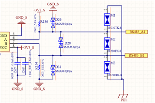
Can you help to review attached SCH for the Auto RX TX issue at 115200 baud rate?
but 9600 baud rate works well here. tks for your comments.
This thread has been locked.
If you have a related question, please click the "Ask a related question" button in the top right corner. The newly created question will be automatically linked to this question.
Hi Allen,
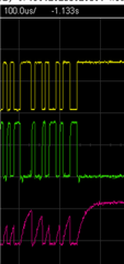
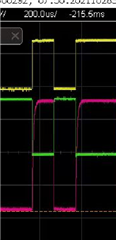
Your schematic shows that the DE and #RE pins are shorted together. When the TX line drives low the RS485 transceiver is able to actively drive the cable side. But when the TX line is driven back high, the DE/#RE is set to a logic low by your BJT circuit making the RS485 transceiver go from an active driver to a high impedance receiver. This means the device is not actively driving the A-B pins in the opposite direction anymore. Instead the cable side is relying on an RC circuit to discharge through leakage. In your second waveform with the 115200 datarate, you can see the A-B pink wave form on Ch4 is seeing an RC time constant discharge. Because the bit period you are sending is faster than the RC time constant, the A-B network isn't able to swing from GND to Vcc in time.
It works with the 9600 waveform because you likely have a slow/wide enough bit period to let the RC circuit discharge in time.
Our recommendation is for you to change your circuit to use a timer circuit like in this TI reference design: https://www.ti.com/lit/ug/tidubw6/tidubw6.pdf?ts=1698434598279&ref_url=https%253A%252F%252Fwww.google.com%252F
Or to potentially use the THVD1406 which include an internal auto direction feature.
-Bobby
Hi Bobby:
after few days check with the sch and logic.
1. When there is no data, TX=1, Q9 is on, DE=RE=0, into receiving mode.
2. When sending data 1, TX=D1=1. Since it is still in the receiving mode and the driver is in a high-impedance state, TX disconnect A/B, and the AB voltage is determined based on the pull-up and pull-down resistors, then A=1,,B= 0, becomes logic 1
3. When sending data 0, TX=0, Q9 is not open, DE=RE=1, the driver is enabled, A=0, B=1, it becomes logic 0.
So i think the SCH is correct.
And base on the theory of cable side is relying on an RC circuit to discharge through leakage, the R=5.1K, and C major to SMAJ6.0 device. So do you means the A-B side need to discharge/ charger via 5.1K and TVS ? And this RC time > Tbit=1/115200=8.6us. then it does not work ?


And i so found that the Type value of THVD1406 tdevice_autodir is 8us, very close to the Tbit when in 115200 baud rate, does it work?
But when work on 9600, Below Tbit=1/9600=104us. and the RC time of A-B like 30us > 104us, so it works. Am i correct?

1. When there is no data, TX=1, Q9 is on, DE=RE=0, into receiving mode.
If TX is =1 then the BJT you have set up will be turned on which will drive DE=0 (disable driver) and /RE to 0(enable receiver).
2. When sending data 1, TX=D1=1. Since it is still in the receiving mode and the driver is in a high-impedance state, TX disconnect A/B, and the AB voltage is determined based on the pull-up and pull-down resistors, then A=1,,B= 0, becomes logic 1
Yes A will be ~3.3V and B will be ~GND so A-B = +VOD or a logic 1. You are relying on an RC constant to generate this voltage where the R is the external resistor values. The C is the cap loading on A/B pins.
3. When sending data 0, TX=0, Q9 is not open, DE=RE=1, the driver is enabled, A=0, B=1, it becomes logic 0.
Tx=0 so BJT is off therefore DE=1 (driver is enabled) and /RE=1 (receivers disabled). This means when you drive a '0' the RS485 transceiver will active drive the signal BUT ONLY WHEN YOU DRIVE '0'. The RC constant still exisits but instead of R = to ~5.1k from the external pull up resistor you get a stronger 'R' from the THVD1400 (R from THVD1400 is much stronger than 5.1k). You can the falling edges on the A-B scopeshot is faster than the rising edges which supports this.
So i think the SCH is correct.
It's correct if you're okay the device only actively driving during TX=0. It does not allow the THVD1400 to drive the signal in the opposite direction when TX=1. This means you won't be able to at speeds faster than the RC constant during the disabled period time.
So do you means the A-B side need to discharge/ charger via 5.1K and TVS ? And this RC time > Tbit=1/115200=8.6us. then it does not work ?
You also need to account for how long it takes the device to switch from the active output into receiver mode. This will eat into the bit period. THVD1400 has a typical time of 4us and a max time of 10us. This would eat into the bit period of the '1' you are trying to send on TX. This makes me think you're Tbit will be 8.6us plus 4us typical (if we assume 1x RC is enough). Your high bit periods will last longer and mess up your bit rate. I really don't think this approach is good for high baud rates because of this. For low baud rates this could work but at higher speeds the disable time is too long and will cause a mismatch on the receiving signal.
And i so found that the Type value of THVD1406 tdevice_autodir is 8us, very close to the Tbit when in 115200 baud rate, does it work?
Yes THVD1406 is the better option than relying on the current set up. The active drive capability will provide better signals on the A-B pins.
My understanding here is with the auto-direction, the device will keep the THVD1406 as an active driver and will only switch back to be a receiver when the TX line goes from low to high for atleast 4us. If you send too many '1's in a row before the next high to low transition on TX, the device would switch back to receive mode.
-Bobby