This thread has been locked.

If you have a related question, please click the "Ask a related question" button in the top right corner. The newly created question will be automatically linked to this question.

TCAN1145-Q1: Regarding TCAN1145-Q1, I would like to communicate with you some technical parameters/functions:

Part Number: TCAN1145-Q1

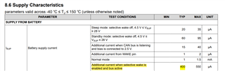
1.Does this current refer to the additional current consumed by the chip when the external bus is in operation when the selective wake-up function is enabled in sleep or standby mode?

2.If we do not use a local wake-up pin (WAKE pin), is it directly connected to ground or grounded through a resistor? What is the recommended value for resistance?

3.Does the WAKE pin allow direct connection to the 5V GPIO pin of the MCU? The MCU is Infineon TC3xx.

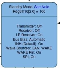
4.Can we achieve full state jump and operation through SPI when we do not use WAKE pins? For example, power on=>Normal Mode, Normal Mode=>Sleep Mode, etc.

Among them, VSUP is 12V normally charged, and VCC/VIO is powered down when the controlled 5V power supply is dormant.

  • Ray,

    Thanks for bringing this to E2E.

    1. This increased current happens if selective wake is enabled, the device is in sleep mode, and then has received a WUP. At this point the WUF detection circuitry turns on, which makes up the increase shown in the datasheet.

    2. The WAKE pin can be directly tied to GND, no resistor needed.

    3. Yes, on the TCAN1145-Q1 the WAKE pin thresholds are set to 5V logic. Even if it isn't used, it can be tied to the 5V GPIO. I'd recommend grounding if not being used though.

    4. Yes, if you look at the state diagram on page 29 of the datasheet, you can see that SPI commands will allow traversal of all modes.

    Regards,

    Eric Hackett