This thread has been locked.

If you have a related question, please click the "Ask a related question" button in the top right corner. The newly created question will be automatically linked to this question.

TCAN4550-Q1: Issue communicating over CAN

Part Number: TCAN4550-Q1
Other Parts Discussed in Thread: TCAN4550, TCAN4550EVM

I am using the TCAN4550-Q1 with the Adafruit Feather ESP32-S2 TFT to control the chip. I have successfully been able to read registers over SPI, as well as write to them using the ESP32. 

I'm now trying to communicate over CAN, and I'm having trouble getting this to work.  I'm quite new to this so its very possible that I've made a trivial error in my setup. I have been referring to the data sheet as well as the TCAN45xx Software User's Guide. 

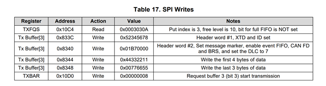
So far, I have configured the CAN timing and MRAM, and read back the TXFQS register to get the put index. I then wrote to the put index, but when reading register 0x1050, the flag for a FIFO message stays as zero. 

Here is the code that I am using thus far: 

#include <SPI.h>

#define CAN1SPI_CS 6
#define CAN2SPI_CS 5
#define CANSPI_CLK 4000000

SPISettings TCAN4550_SPI_settings(CANSPI_CLK, MSBFIRST, SPI_MODE0);
byte receivedDat[4];
byte writeData[4];

byte setupReg[] = {0b11001000, 0, 0b00000110, 0b10101010};
byte canTimer[] = {2, 3, 6, 1}; // sync jump, prescaler, tq before sample point, tq after sample point - values will be intepreted as val + 1 (i.e. 3,4,7,2)
byte canCONTROL[] = {0,0,0,0b00001011};
byte SIDFC[] = {0,0x02,0, 0};
byte XIDFC[] = {0,0x01,0,0x08};
byte RXF0C[] = {0x02,0x04,0,0x10};
byte RXF1C[] = {0x03,0x05,0,0xF0};
byte RXBC[] = {0,0,0,0};
byte RXESC[] = {0,0,0,0x76};
byte TXEFC[] = {0x02, 0x03, 0x02, 0x58};
byte TXBC[] = {0x0A,0,0x02,0x70};
byte TXESC[] = {0,0,0,0x07};  
byte TXbuffer1[] = {0x52, 0x34, 0x56, 0x78};
byte TXbuffer2[] = {0x01, 0x87, 0, 0}; //changed configuration from example to have CAN FD and bit rate switching disabled
byte TXbuffer3[] = {0x44, 0x33, 0x22, 0x11}; //dummy data
byte TXbuffer4[] = {0x00, 0x77, 0x66, 0x55}; //dummy data
byte TXBAR[] = {0, 0, 0, 0b00000001};
void setup() {
// put your setup code here, to run once:
  Serial.begin(921600);
  pinMode(CAN1SPI_CS, OUTPUT);
  pinMode(CAN2SPI_CS, OUTPUT);

  digitalWrite(CAN1SPI_CS, HIGH);
  digitalWrite(CAN2SPI_CS, HIGH);
  SPI.begin();

  // set modes and pin config register
  setRegister(0x0800, setupReg, 4);

  //set CAN bit timing
  changeState("standby");

  // In standby set CAN timing /////////////////////////////////////////////////////////////////////////////
  setRegister(0x101C, canTimer, 4);
  setRegister(0x1018, canCONTROL, 4);

  // SET MRAM
  setRegister(0x1084, SIDFC, 4);
  setRegister(0x1088, XIDFC, 4);
  setRegister(0x10A0, RXF0C, 4);
  setRegister(0x10B0, RXF1C, 4);
  setRegister(0x10AC, RXBC, 4);
  setRegister(0x10BC, RXESC, 4);
  setRegister(0x10F0, TXEFC, 4);
  setRegister(0x10C0, TXBC, 4);
  setRegister(0x10C8, TXESC, 4);

  // Change state back to normal, should be ready for CAN communication
  changeState("normal");

  delay(50);
}
void loop() {
  readRegister(0x0800, "BIN");

  //Read interrupt register
  // read0820();

  //try to reset register interrupt register
  // setRegister(0x0820, reset0820, 4);

  //  Read TXFQS register bits 20:16 to get "put" register (currently reading back 1 at 16th bit)
  readRegister(0x10C4, "HEX");

  //Try writing to TX Buffer
  setRegister(0x82B8, TXbuffer1, 4); //Put index was 0x01, start of TX buffer section is 0x8270 so write to 0x8270 + 0x48*0x01 (element size)
  setRegister(0x82BC, TXbuffer2, 4);
  setRegister(0x82B0, TXbuffer3, 4);
  setRegister(0x82B4, TXbuffer4, 4);
  setRegister(0x10D0, TXBAR, 4);

  readRegister(0x1050, "BIN");
}
Read register, set register and change state are functions that I wrote that I have verified are working as intended. 
When I read register 0x1050, its giving me "0x00300800".
Thanks in advance!
  • Hi Ally,

    There are a couple things I can suggest right away.  First, the value of 0x00300800 for register 0x1050 indicates the Bit Error Uncorrected and Corrected bits are set.  This can happen if you don't first "zero out" the MRAM and the bits power up to an unknown state.  Then when the Error Correction Code is calculated, it results in an error due to some of the bits having an incorrect value.

    Is there a way to verify or read back the register values through a terminal or JTAG debugger to verify they are getting set to your intended values?  If so, can you provide the final values of the device register configuration for review?

    The Control Register 0x1018 has two bits that both need to be set to '1' in order for all of the MCAN Protected Registers indicated by RP in the datasheet to be accessible.  These are the INIT and CCE bits 0x1018[1:0].  Here is the tricky part.  The INIT bit needs to be set to "1" prior to the CCE bit getting set to "1".  Then the CCE bit needs to be set to "1" prior to any RP bits in any other register.  This means that the Control register 0x1018 usually requires at least 2 writes to unlock the protected bits and allow them to be configured. 

    I only see one write to the Control register in your sequence, so there is a good chance your not actually configuring the write protected registers.  Once you are done with your configuration sequence you should set the CCE and INIT bits back to "0" with a final write to the control register 0x1018. 

    Also note that changing the device state to Standby Mode will force the INIT bit to "1".  But changing the device to Normal mode does not automatically set the INIT bit to "0".

    Once we can verify all the registers are getting properly set and the MRAM is getting initialized to 0's, we can see what else needs to be addressed.

    The TCAN4550-Q1 uses the MCAN IP developed by Bosch for the CAN FD controller.  There is a lot of useful information in the MCAN User's Guide published by Bosch that could not be included in the TCAN4550-Q1 datasheet.  So I would point you to it as an additional reference.  (Link). The only important thing to note is that the TCAN4550 has added an offset of 0x1000 to each MCAN address.  Therefore, the Control register in the TCAN4550 is address 0x1018, but is listed as 0x18 in the MCAN User's Guide.  Other than that the MCAN information is all applicable for the TCAN4550-Q1.

    On that note as well, the TCAN4550 registers that have an address less than 0x1000 are not part of MCAN and were added by TI and handle the non-CAN related device functions.

    Regards,

    Jonathan

  • Hi Jonathan, thanks for your reply! 

    I updated the code to have two separate writes to register 0x1018 as you suggested, setting INIT and CCE separately. However, I think my MRAM was previously configured correctly, as I checked by reading the registers after setting it and the results were as expected. Regardless, I have read out the registers again after setting and this is what I'm getting: 

    Address: 1084: 00020000

    Address: 1088: 00010008

    Address: 10A0: 02040010

    Address: 10B0: 030500F0

    Address: 10F0: 02030258

    Address: 10C0: 0A000270

    Address: 10C8: 00000007

    I don't really understand the process for zeroing out the MRAM, would you be able to explain how thats done a bit more? Does not zeroing it out cause an issue with how the MRAM is configured, or an issue with trying to write the TX Buffers? 

    Thank you! 

    Ally 

  • I wrote zeros to all of the registers in MRAM (0x8000 to 0x8600) that I configured and that seems to have cleared the BEU error, so thank you for that! 

    Now, when I read register 0x10C4 to get the put index, its reading back 00010009. 

    from my understanding, this means the put index is 1, and therefore the address I write the data to should be the start of the Tx Buffer section in memory (0x8270) plus 1 * the element size (0x048), which is 0x82B8. 

    However, when I try and write data, then read register 1050 to see if the Tx FIFO is full, 1050 is reading back as: 29800800, indicating arbitration error and access to a reserved address. 

    I have attached my code again to support this questions. 

    Thank you! 

    #include <SPI.h>

    #define CAN1SPI_CS 6
    #define CAN2SPI_CS 5
    #define CANSPI_CLK 4000000

    SPISettings TCAN4550_SPI_settings(CANSPI_CLK, MSBFIRST, SPI_MODE0);
    byte receivedDat[4];
    byte writeData[4];

    byte setupReg[] = {0b11001000, 0, 0b00000110, 0b10101010};
    byte canTimer[] = {2, 3, 6, 1}; // sync jump, prescaler, tq before sample point, tq after sample point - values will be intepreted as val + 1 (i.e. 3,4,7,2)
    byte canCONTROL[] = {0,0,0,0b00001011};
    byte setCCE[] = {0,0,0,0b00001011};
    byte setINIT[] = {0,0,0,0b00001001};
    byte clearINIT[] = {0,0,0,0b00001000};

    byte SIDFC[] = {0,0x02,0, 0};
    byte XIDFC[] = {0,0x01,0,0x08};
    byte RXF0C[] = {0x02,0x04,0,0x10};
    byte RXF1C[] = {0x03,0x05,0,0xF0};
    byte RXBC[] = {0,0,0,0};
    byte RXESC[] = {0,0,0,0x76};
    byte TXEFC[] = {0x02, 0x03, 0x02, 0x58};
    byte TXBC[] = {0x0A,0,0x02,0x70};
    byte TXESC[] = {0,0,0,0x07};  
    byte TXbuffer1[] = {0x52, 0x34, 0x56, 0x78};
    byte TXbuffer2[] = {0x01, 0x87, 0, 0}; //changed configuration from example to have CAN FD and bit rate switching disabled
    byte TXbuffer3[] = {0x44, 0x33, 0x22, 0x11}; //dummy data
    byte TXbuffer4[] = {0x00, 0x77, 0x66, 0x55}; //dummy data
    byte TXBAR[] = {0, 0, 0, 0b00000001};
    byte clear[] = {0b00000000, 0b00000000, 0b00000000, 0b00000000};
    byte clear0C[] = {0, 0, 0, 0};
    byte reset0820[] = {0, 0b00010100, 0, 0};
    byte clearInterrupts[] = {0xFF, 0b00000000, 0b00000000, 0b00000000};
    /*************************************************************************/

    void setup() {
    // put your setup code here, to run once:
      Serial.begin(921600);
      pinMode(CAN1SPI_CS, OUTPUT);
      pinMode(CAN2SPI_CS, OUTPUT);

      digitalWrite(CAN1SPI_CS, HIGH);
      digitalWrite(CAN2SPI_CS, HIGH);
      SPI.begin();

      // set modes and pin config register
      setRegister(0x0800, setupReg, 4);

      //set CAN bit timing
      // changeState("standby");

      // In standby set CAN timing /////////////////////////////////////////////////////////////////////////////
      setRegister(0x101C, canTimer, 4);
      setRegister(0x1018, setINIT, 4);
      setRegister(0x1018, setCCE, 4);

      // SET MRAM
      setRegister(0x1084, SIDFC, 4);
      setRegister(0x1088, XIDFC, 4);
      setRegister(0x10A0, RXF0C, 4);
      setRegister(0x10B0, RXF1C, 4);
      setRegister(0x10AC, RXBC, 4);
      setRegister(0x10BC, RXESC, 4);
      setRegister(0x10F0, TXEFC, 4);
      setRegister(0x10C0, TXBC, 4);
      setRegister(0x10C8, TXESC, 4);

      // Change state back to normal, should be ready for CAN communication
      changeState("normal");
      setRegister(0x1018, clearINIT, 4);
      // setRegister(0x0830, clearInterrupts, 4);
      // setRegister(0x0820, reset0820, 4);
      word curr_address = 0x8000;
      while (curr_address < 0x8500){
        setRegister(curr_address, clear, 4);
        curr_address = curr_address + 8;
      }
      delay(50);
    }

    void loop() {

      //  Read TXFQS register bits 20:16 to get "put" register (bits 20:16) (currently reading back 1 at 16th bit)
      readRegister(0x10C4, "HEX");

      //Try writing to TX Buffer
      setRegister(0x82B8, TXbuffer1, 4); //Put index was 0x01, start of TX buffer section is 0x8270 so write to 0x8270 + 0x48*0x01 (element size)
      setRegister(0x82BC, TXbuffer2, 4);
      setRegister(0x82C0, TXbuffer3, 4);
      setRegister(0x82C4, TXbuffer4, 4);
      setRegister(0x10D0, TXBAR, 4);
     
      read1050();

        delay(1000);

    }
  • Hi Ally,

    I'm glad you got the protected registers and the BEU, BEC errors cleared up.  When the device is powered up, there is no Reset mechanism connected to the MRAM cells and they can power up with an unknown value.  Typically the MRAM powers up with a zero for each byte cell, but some can have a non-zero value.  

    The ECC calculation assumes the memory has been initialized to zero if it has not had a value written to it, so the BEU and BEC errors can occur if you do not explicitly write a 0x00 to each and every MRAM cell you are enabling.  You need to do this before you write your TX message to the TX Buffer or you need to write 0x00's to every unused cell that is enabled.

    Have you looked at the TCAN4550 Demo Software (SLLC469) as a reference? You can find the link to download on the TCAN4550-Q1 Product folder (Link) or from this direct (Link).  It is mostly ANSI-C code that can be generally used with most MCU's that are programmed in C.  The SPI drivers and GPIO hardware pin configuration would need to be updated to match the specific MCU being used.  But it may be a good reference.

    Address: 1084: 00020000

    You are configuring 2 SID Filter Elements.  Are you actually writing the MRAM space with filters?  If you enable filters in MRAM, you must actually have a filter.  This is because when a CAN message is received the MCAN controller will cycle through the list of filters and comparing the message ID and determine what to do with the message (store it or ignore it).  If you have enabled a filter but not actually written one the MRAM, then the RX process will error out when it tries to compare the message with the empty filter element.  This is not an issue for transmitting messages, but I didn't see where you wrote the filters to MRAM that you have enabled.  The same goes for XID

    I think your MRAM addressing is off starting with the TXEFC starting address.  If I'm interpreting your register values correctly, you want 4 RX FIFO 0 elements with a data payload of 48 bytes.  Each buffer element will take up 14 words (2 for the header + 12 for the 48 bytes of data).

    Then you want 5 RX FIFO 1 elements with a data payload of 64 bytes.  Each buffer element will take up 18 words (2 for the header + 16 for the 64 bytes of data).

    I believe the next available MRAM section should have a start address of 0x258.  I think you are trying to assign the next section to the TX Event FIFO (TXEFC) with a starting address of 0x58 instead.  This will then also cause a problem with your TX Buffers.  If you have 3 TXEFC elements, then I believe the TX Buffers should have a starting address of 0x270.

    Please double check my calculations and interpretation of your desired configuration and verify the MRAM address allocation.  But I think you may not be writing your TX message to the correct section of MRAM and that may be why you can't send a message.

    Regards,

    Jonathan

  • Hi Jonathan, 

    You've completely lost me here. I've been primarily following the example for writing to CAN detailed in the TCAN 45xx software guide. The only thing I changed is the addresses that I'm writing to, based on what I'm reading back as the put index from TXFQS. I've attached an image of the table of writes I am referring to. I configured my MRAM the same way that was done in this example. 

    In this example, the put index was 3, and so they calculated the address to write to as 0x48 (element size) * 0x3 + section start address. I followed this same process, but using a put index of 1 to determine the address to write to. I also think that I am filling the MRAM space with filters in the first two writes, based on the example? But I am unsure of this. 

  • Hi Ally,

    I'm sorry to confuse you.  I missed that you were trying to directly follow the configuration in the Software User's Guide and I was trying to determine your configuration and look for errors based on decoding your register values, so knowing what you are trying to do is helpful.

    The TCAN4550 uses the MCAN CAN FD Controller IP developed by Bosch, so I will also point you to the MCAN User's Manual published by Bosch. (Link).  It contains additional information about the MCAN features that could not be incorporated into the documents published by TI.

    I also think that I am filling the MRAM space with filters in the first two writes, based on the example? But I am unsure of this. 

    For the SID and XID Filters, you are configuring space in MRAM for the filters with the SIDFC and XIDFC configuration registers, but I don't see any filters actually written to the MRAM that contains the Message ID, filter type (classic bit mask or range filter, etc.).

      // SET MRAM
      setRegister(0x1084, SIDFC, 4);
      setRegister(0x1088, XIDFC, 4);

    If you enable 2 SID filters with start address 0x8000, you will need to write a SID filter to MRAM address 0x8000 and another to 0x8004.  Then with one XID filter element, you will need to write that filter to MRAM address 0x8008.  SID filters are only a single word of memory, and XID filters are two words of memory. 

    These filters may not be causing your TX issues, but this will be a problem when you try to receive a message.  See section 2.4 of MCAN User's Manual for more detailed information.

    The TX FIFO should start off with an initial Put Index value of "0" so the TX Buffer element to use for your first TX message should be Index "0".  From your code, I'm not sure how or why you are getting the Put Index increased to 1 before your first message.

    However, if you are writing your TX message element to the MRAM index "1" location, you would also need to change the value of your TXBAR byte to match the index location you have used in MRAM.  Your codes shows bit "0" is set for index position "0" so when you write to the TXBAR register 0x10D0 with a value of 0x00000001, it will try to send the message located at MRAM start address which is 0x8270 according to your MRAM configuration.

    Can you try using index "0" for your first TX message instead of index "1" and see if that changes anything?

    Regards,

    Jonathan

  • Hi Jonathan, 

    I will try that for the TX Buffers, thank you!

    Regarding the filters - is it possible to just not have SID and XID filters? In which case I will change my MRAM configuration to reflect this. Just not sure if these are required or if there are specific negative repercussions to not having them.

    Thanks again for all of your help :) 

    Ally 

  • Hi Ally,

    Yes you simply leave the SIDFC (0x1084) and XIDFC (0x1088) registers as default values, or comment them out of your code.  You don't need to make any changes to the start address allocation of any other MRAM elements because the requirement is the sections do not overlap.  You can have gaps or arrange your sections in any way you like.  As long as the SID and XID list sizes are have a value of zero, MCAN will not try to use them when receiving a message.

    In order to have multiple RX FIFOs you will need to have filters setup to direct the messages to the appropriate RX FIFO.  By default all your RX messages would get stored in RX FIFO 0, so you really don't need to configure RX FIFO 1 if you don't have filters because it will simply be unused. 

    If you wanted to really simplify your test setup to see a CAN message get transmitted, you could start with using the "Dedicated TX Buffers" and not the TX FIFO.  This would allow you 100% control over which buffer element is used for storing the message and the corresponding TXBAR bit you set.  You could simply swap the value of the TFQS and NDTB register fields in the TXBC (0x10C0) register and keep the start address the same.  This way you just have to write the TX message to the MRAM buffer and set the TXBAR bit to '1' every time you want to send the message.  If you don't re-write the TX buffer, that same message can be sent over and over again every time you set the TXBAR bit.

    Once you get that working and a better understanding of how the device works, then you can add the FIFO get/put index code if you like.

    Regards,

    Jonathan

  • Hi Jonathan,

    Thanks for the advice with the FIFOs. I commented out the MRAM allocations for SIDFC and XIDFC.I changed the address for 0x10C0 when configuring MRAM to be 000A0270. I also changed TXBAR to be just zeros. Otherwise, my code is the same as above, but in the loop I have the following: 

      //Try writing to TX Buffer
      setRegister(0x8270, TXbuffer1, 4); 
      setRegister(0x8274, TXbuffer2, 4);
      setRegister(0x827C, TXbuffer3, 4);
      setRegister(0x8280, TXbuffer4, 4);
      setRegister(0x10D0, TXBAR, 4);

    Now, there aren't any errors when reading register 1050, however the register is reading back only zeros. I am unsure why the Rx FIFO bit is not set ? 

    Kind regards,

    Ally 

  • Hi Ally,

    I want to clarify we are setting the bit in the TXBAR register correctly.  Writing all zero's to TXBAR won't transmit a message.

    There can be up to 32 TX Buffer elements enabled.  You are now enabling 10 of them with the new value of register 0x10C0.

    Each bit in the TXBAR register corresponds to one of the TX Buffer elements and the device will try to transmit the message held in the MRAM buffer location that corresponds to the TXBAR bit.  Therefore, when you store a message in the first TX Buffer "0" with a start address of 0x8270, you will then need to set bit "0" of the TXBAR register to a value of "1" to send the message.  This means you would write 0x00000001 to 0x10D0.

    If you wanted to send a message from the last enabled TX Buffer element, this would have an index of "9" so you would write your message to MRAM and then set the 9th bit in the TXBAR register to a value of "1".  This means you would write 0x00000200 to register 0x10D0.

    Also, you can set multiple TXBAR bits at a time and the device will try to transmit the message in each TX Buffer that corresponds to a "1".

    Now, there aren't any errors when reading register 1050, however the register is reading back only zeros. I am unsure why the Rx FIFO bit is not set ? 

    What are you connecting to the TCAN4550 device that will receive and acknowledge the message on the CAN bus?

    Are you trying to do some form of loop back testing that would cause the RX FIFO to also receive the same message it just transmitted? 

    You will either need to have another CAN device connected to the TCAN4550 that will send a message that will be received in the RX FIFO.  Or you will need to enable one of the Loop Back modes.

    There are two different types of loopback that can be configured.

    If you want the device configured for Internal Loop Back Mode, the TEST.LBCK bit (0x1010.4) should be set to '1' which enables the TX data to loop back to the RX.  Also, the CCCR.MON bit (0x1018.5) should be set which disconnects the TX data from reaching the CAN bus. 

    However, if you clear the CCCR.MON bit, or set it to '0', this will configure the device for an External loop back mode which will allow the TX data to be output on the CAN bus as well as looped back to the RX input.  The external CAN bus data will not reach the RX input in this mode.  The following image is taken from the Bosch M_CAN User's Guide and is a good illustration of how the device is configured.

    Regards,

    Jonathan

  • Hi Jonathan, 

    Thank you again. I am now getting Protocol Error in Arbitration Phase on 1050, and I don't understand why. I've attached my updated code.

    #include <SPI.h>

    #define CAN1SPI_CS 6
    #define CAN2SPI_CS 5
    #define CANSPI_CLK 4000000

    SPISettings TCAN4550_SPI_settings(CANSPI_CLK, MSBFIRST, SPI_MODE0);
    byte receivedDat[4];
    byte writeData[4];

    byte setupReg[] = {0b11001000, 0, 0b00000110, 0b10101010};
    byte canTimer[] = {2, 3, 6, 1}; // sync jump, prescaler, tq before sample point, tq after sample point - values will be intepreted as val + 1 (i.e. 3,4,7,2)
    byte canCONTROL[] = {0,0,0,0b00001011};
    byte setCCE[] = {0,0,0,0b00001011};
    byte setINIT[] = {0,0,0,0b00001001};
    byte clearINIT[] = {0,0,0,0b00101000};

    byte SIDFC[] = {0,0x02,0, 0};
    byte XIDFC[] = {0,0x01,0,0x08};
    byte RXF0C[] = {0x02,0x04,0,0x10};
    byte RXF1C[] = {0x03,0x05,0,0xF0};
    byte RXBC[] = {0,0,0,0};
    byte RXESC[] = {0,0,0,0x76};
    byte TXEFC[] = {0x02, 0x03, 0x02, 0x58};
    // byte TXBC[] = {0x0A,0,0x02,0x70}; configured for FIFO
    byte TXBC[] = {0x00,0x0A,0x02,0x70}; // configured for Buffers
    byte TXESC[] = {0,0,0,0x07};  
    byte TXbuffer1[] = {0x52, 0x34, 0x56, 0x78};
    byte TXbuffer2[] = {0x01, 0x87, 0, 0}; //changed configuration from example to have CAN FD and bit rate switching disabled
    byte TXbuffer3[] = {0x44, 0x33, 0x22, 0x11}; //dummy data
    byte TXbuffer4[] = {0x00, 0x77, 0x66, 0x55}; //dummy data
    byte TXBAR[] = {0, 0, 0, 0x01};
    byte clear[] = {0b00000000, 0b00000000, 0b00000000, 0b00000000};
    byte clear0C[] = {0, 0, 0, 0};
    byte reset0820[] = {0, 0b00010100, 0, 0};
    byte testReg[] = {0, 0, 0, 0x10};
    byte clearInterrupts[] = {0xFF, 0b00000000, 0b00000000, 0b00000000};
    /*************************************************************************/

    void setup() {
    // put your setup code here, to run once:
      Serial.begin(921600);
      pinMode(CAN1SPI_CS, OUTPUT);
      pinMode(CAN2SPI_CS, OUTPUT);

      digitalWrite(CAN1SPI_CS, HIGH);
      digitalWrite(CAN2SPI_CS, HIGH);
      SPI.begin();

      // set modes and pin config register
      setRegister(0x0800, setupReg, 4);

      //set CAN bit timing
      // changeState("standby");

      // In standby set CAN timing /////////////////////////////////////////////////////////////////////////////
      setRegister(0x101C, canTimer, 4);
      setRegister(0x1018, setINIT, 4);
      setRegister(0x1018, setCCE, 4);

      // SET MRAM
      // setRegister(0x1084, SIDFC, 4);
      // setRegister(0x1088, XIDFC, 4);
      setRegister(0x10A0, RXF0C, 4);
      setRegister(0x10B0, RXF1C, 4);
      setRegister(0x10AC, RXBC, 4);
      setRegister(0x10BC, RXESC, 4);
      setRegister(0x10F0, TXEFC, 4);
      setRegister(0x10C0, TXBC, 4);
      setRegister(0x10C8, TXESC, 4);

      // Change state back to normal, should be ready for CAN communication
      changeState("normal");
      setRegister(0x1018, clearINIT, 4);
      setRegister(0x1010, testReg, 4);

      // Clear MRAM
      word curr_address = 0x8000;
      while (curr_address < 0x8500){
        setRegister(curr_address, clear, 4);
        curr_address = curr_address + 8;
      }
      delay(50);
    }

    void loop() {
      //Try writing to TX Buffer
      setRegister(0x8270, TXbuffer1, 4);
      setRegister(0x8274, TXbuffer2, 4);
      setRegister(0x827C, TXbuffer3, 4);
      setRegister(0x8280, TXbuffer4, 4);
      setRegister(0x10D0, TXBAR, 4);
      read1050();

        delay(1000);

    }
  • Hi Ally,

    Protocol errors in both the Arbitration (Nominal) and Data phases usually are because of incompatible bit timing configurations for the different devices on the CAN bus.  All nodes on a CAN bus should generally be configured with the same Nominal and Data bit timing parameters so that they are sending and receiving/sampling the data in the same way.  If the configurations are different, then they may sample the data incorrectly and create a bit error resulting in one of the various types of protocol errors.

    Nominal Bit Timing & Prescaler Register (NBTP) 0x101C

    Data Bit Timing & Prescaler Register (DBTP) 0x100C

    Transmitter Delay Compensation Register (TDCR) 0x1048 (if using CAN FD)

    I see that you are configuring your NBTP register 0x101C, but I don't see where you are configuring the DBTP register 0x100C.  The device is likely trying to transmit with the default register values which are incorrect for your application and are likely the reason for the protocol errors.

    Regards,

    Jonathan

  • Hi Jonathan,

    I updated the bit timing for register 0x100C and the arbitration error seems to have disappeared, so thank you!

    I am trying to set register 1010 so that I can be in loop back mode, however when I read back the register it doesn't reflect the values I'm writing to it. I noticed that it is RP, so I am writing to it in the same section where I set MRAM (after setting CCE and INIT). I also set CCCR.TEST to 1. When I read back address 1010, I'm getting 0x00000080. 

    Further, in register 0820, I'm getting a CAN silent error.

    Thanks! 

    Ally 

  • Hi Ally,

    I'm glad we are making progress!

    The LPBK bit in the TEST register is RP as you noted.  The only reason I know that would prevent you from setting it is that the INIT and CCE bits are not both equal to 1 prior to you trying to write to this register.  Perhaps try writing to this register multiple times or do a read verify after the write to see if has been unprotected.  I have not seen issues with the protected registers not being able to be updated if both INIT and CCE bits are set to "1".  My only suggestions on this issue is to double check the code and if needed add duplicate writes to the CCCR register to ensure all bits are set and then do a read-verify if to help pinpoint the problem.

    For additional reference, this E2E thread has a lot of detailed information on configuring Loopback that you may want to reference. (Link).

    The CAN Silent Error simply means that there has not been any activity on the CAN bus for approximately 1 second.  This is part of a failsafe feature that can help detect a fault condition such as where the device has been physically disconnected from the CAN bus.  If the Failsafe Mode is enabled, a CAN Silent error for approximately 4 minutes could cause the device to enter sleep mode.  By default Failsafe Mode is disabled, so you can generally ignore the CAN Silent error.

    Regards,

    Jonathan

  • Hi Jonathan. 

    Managed to find the problem, I was just setting it wrong sorry about that! Loop back mode has now been set. I also set CCR.MON. I'm now trying to send a message, and I'm having the same issue as before where it seems the Rx FIFO never gets set to full. 

    This is the only code I have in the loop: 

      //Try writing to TX Buffer
      setRegister(0x8270, TXbuffer1, 4);
      setRegister(0x8274, TXbuffer2, 4);
      setRegister(0x827C, TXbuffer3, 4);
      setRegister(0x8280, TXbuffer4, 4);
      setRegister(0x10D0, TXBAR, 4);
    also the definitions of those variables: 
    byte TXbuffer1[] = {0x52, 0x34, 0x56, 0x78};
    byte TXbuffer2[] = {0x01, 0x87, 0, 0}; //changed configuration from example to have CAN FD and bit rate switching disabled
    byte TXbuffer3[] = {0x44, 0x33, 0x22, 0x11}; //dummy data
    byte TXbuffer4[] = {0x00, 0x77, 0x66, 0x55}; //dummy data
    byte TXBAR[] = {0, 0, 0, 0x01};
    I read back register 10CC, and it reads 0x00000001, which i believe is correct. I tried reading back register 0x10D8 to see if it is ever set indicating the transmission occurred, but I'm getting all zeros there. I'm also getting all zeros in register 1050. I've confirmed I'm in normal mode, is there something else I'm missing that is required in order to transmit a message? 
  • I'm no longer getting a CAN silent error so it seems like there is activity on the CAN bus but I can't seem to figure out where

  • If you are seeing the TXBRP bit getting set (0x10CC[0]) then the device should be trying to transmit the message and waiting for an ACK.  In Loopback mode, it is supposed to ignore ACK errors for self test purposes, so we should see the message in the RX FIFO. 

    Can you provide me a list of the final TCAN4550 configuration in the form of a register address and value?  If so I can program those values into an EVM and then more easily debug this and provide you feedback.

    Regards,

    Jonathan

  • Hi Jonathan,

    Here's my full code:

    #include <SPI.h>

    #define CAN1SPI_CS 6
    #define CAN2SPI_CS 5
    #define CANSPI_CLK 4000000

    SPISettings TCAN4550_SPI_settings(CANSPI_CLK, MSBFIRST, SPI_MODE0);
    byte receivedDat[4];
    byte writeData[4];

    byte setupReg[] = {0b11001000, 0b00100000, 0b00000110, 0b10101010};

    byte canTimer[] = {2, 3, 6, 1}; // sync jump, prescaler, tq before sample point, tq after sample point - values will be intepreted as val + 1 (i.e. 3,4,7,2)
    byte canCONTROL[] = {0,0,0,0b00001011};

    // Control registers to allow access to protected write registers
    byte setCCE[] = {0,0,0,0b10111011};
    byte reset1018[] = {0,0,0,0x99};
    byte clearINIT[] = {0,0,0,0b10110000};

    byte SIDFC[] = {0,0x02,0, 0};
    byte XIDFC[] = {0,0x01,0,0x08};
    byte RXF0C[] = {0x02,0x04,0,0x10};
    byte RXF1C[] = {0x03,0x05,0,0xF0};
    byte RXBC[] = {0,0,0,0};
    byte RXESC[] = {0,0,0,0x76};
    byte TXEFC[] = {0x02, 0x03, 0x02, 0x58};
    // byte TXBC[] = {0x0A,0,0x02,0x70}; configured for FIFO
    byte TXBC[] = {0x00,0x0A,0x02,0x70}; // configured for Buffers
    byte TXESC[] = {0,0,0,0x07};  
    byte TXbuffer1[] = {0x52, 0x34, 0x56, 0x78};
    byte TXbuffer2[] = {0x01, 0x87, 0, 0}; //changed configuration from example to have CAN FD and bit rate switching disabled
    byte TXbuffer3[] = {0x44, 0x33, 0x22, 0x11}; //dummy data
    byte TXbuffer4[] = {0x00, 0x77, 0x66, 0x55}; //dummy data
    byte TXBAR[] = {0, 0, 0, 0x01};
    byte clear[] = {0b00000000, 0b00000000, 0b00000000, 0b00000000};
    byte clear0C[] = {0, 0, 0, 0};
    byte reset0820[] = {0, 0b00010100, 0, 0};
    byte testReg[] = {0, 0, 0, 0b00010000};
    byte clearInterrupts[] = {0xFF, 0b00000000, 0b00000000, 0b00000000};
    /*************************************************************************/

    void setup() {
    // put your setup code here, to run once:
      Serial.begin(921600);
      pinMode(CAN1SPI_CS, OUTPUT);
      pinMode(CAN2SPI_CS, OUTPUT);

      digitalWrite(CAN1SPI_CS, HIGH);
      digitalWrite(CAN2SPI_CS, HIGH);
      SPI.begin();
      // while (!Serial) {
      //   delay(10);
      // }
      // set modes and pin config register
      setRegister(0x0800, setupReg, 4);

      //set CAN bit timing
      changeState("standby");

      // In standby set CAN timing /////////////////////////////////////////////////////////////////////////////
      setRegister(0x1018, reset1018, 4); //set INIT bit
      setRegister(0x1018, setCCE, 4); //set CCE
      setRegister(0x101C, canTimer, 4); //set CAN timing NBTP
      setRegister(0x100C, canTimer, 4); //set CAN timing DBTP
      setRegister(0x1010, testReg, 4); //set loop back mode

      // SET MRAM
      setRegister(0x10A0, RXF0C, 4);
      setRegister(0x10B0, RXF1C, 4);
      setRegister(0x10AC, RXBC, 4);
      setRegister(0x10BC, RXESC, 4);
      setRegister(0x10F0, TXEFC, 4);
      setRegister(0x10C0, TXBC, 4);
      setRegister(0x10C8, TXESC, 4);

      // Change state back to normal, should be ready for CAN communication
      changeState("normal");

      //clear INIT bit
      setRegister(0x1018, clearINIT, 4);

      // zero MRAM
      word curr_address = 0x8000;
      while (curr_address < 0x8500){
        setRegister(curr_address, clear, 4);
        curr_address = curr_address + 8;
      }
     
      delay(50);
    }

    void loop() {

      //Try writing to TX Buffer
      setRegister(0x8270, TXbuffer1, 4);
      setRegister(0x8274, TXbuffer2, 4);
      setRegister(0x827C, TXbuffer3, 4);
      setRegister(0x8280, TXbuffer4, 4);
      setRegister(0x10D0, TXBAR, 4); //check 10CC to see if bit has been properly set

      read1050();

      readRegister(0x10A4, "BIN"); //check Rx FIFO 0 status register
      readRegister(0x8270, "HEX"); // start address of Rx FIFO 0, should read back  
      delay(1000);

    }

    // Set device state (sleep, standby, normal) //////////////////////////////////
    void changeState(char state[]){
      byte setbyte;
      if (state == "normal"){
        setbyte = 0b10101010; //first two bits 10 for normal
      }else if (state == "standby"){
        setbyte = 0b01101010; //first two bits 01 for standby
      }else if (state == "sleep"){
        setbyte = 0b00101010; //enter sleep mode, first two bits 00
      }

      setupReg[3] = setbyte;
      setRegister(0x0800, setupReg, 4);

    }

    // Write into register ////////////////////////////////////////////////////////
    void setRegister(short regAddress, byte sendDat[], int nBytes){
      SPI.beginTransaction(TCAN4550_SPI_settings);    
      digitalWrite(CAN1SPI_CS, LOW);
      SPI.transfer(0x61); //write command
      SPI.transfer16(regAddress); //send address to write to
      SPI.transfer(0x01); //length of data to write (0x01 is 32 bits?)

      for(int i = 0; i < nBytes; i++){
          SPI.transfer(sendDat[i]);
      }
     
      digitalWrite(CAN1SPI_CS, HIGH);
      SPI.endTransaction();
    }

    // Read register out to serial monitor ////////////////////////////////////////
    void readRegister(short regAddress, char encoding[]){

      SPI.beginTransaction(TCAN4550_SPI_settings);    
      digitalWrite(CAN1SPI_CS, LOW);

      SPI.transfer(0x41); //read command
      SPI.transfer16(regAddress); //send address of reg to read
      SPI.transfer(0x01); //length of data expected back

      //recieve data
      for(int i = 0; i < 4; i++){
        receivedDat[i] = SPI.transfer(0x00); //transfer dummy zeros to read out register vals
      }

      digitalWrite(CAN1SPI_CS, HIGH);
      SPI.endTransaction();

      // Read to serial monitor
      Serial.println("Address: ");
      Serial.println(regAddress, HEX);

      if (encoding == "HEX"){
        for(int i = 0; i < 4; i++){
          Serial.println(receivedDat[i],HEX);
        }
        Serial.println();
      }else{
        for(int i = 0; i < 4; i++){
          Serial.print("byte ");
          Serial.print(i);
          Serial.print(": ");
          Serial.println(receivedDat[i],BIN);
        }
      }
    }

    // Read interrupt register ////////////////////////////////////////////////////
    void read0820(){
      SPI.beginTransaction(TCAN4550_SPI_settings);    
      digitalWrite(CAN1SPI_CS, LOW);

      SPI.transfer(0x41); //read command
      SPI.transfer16(0x0820); //send address of reg to read
      SPI.transfer(0x01); //length of data expected back

      //recieve data
      for(int i = 0; i < 4; i++){
        receivedDat[i] = SPI.transfer(0x00); //transfer dummy zeros to read out register vals
      }

      // End transaction
      digitalWrite(CAN1SPI_CS, HIGH);
      SPI.endTransaction();

      // Read out to serial monitor
      Serial.println("////////////////// Reading 0820 //////////////////");

      // FIRST BYTE [31:24] //////////////////////////////
      // only first bit has data
      Serial.print("First Byte: ");
      Serial.println(receivedDat[0], BIN);
     
      if (bitRead(receivedDat[0], 7) == 1){
        Serial.println("CAN Bus normal");
      }

      // SECOND BYTE [23:16] //////////////////////////////
      // bit 17 rsvd so not printed
      Serial.print("Second Byte: ");
      Serial.println(receivedDat[1], BIN);
      if (bitRead(receivedDat[1], 7) == 1){
        Serial.println("Sleep mode");
      }if (bitRead(receivedDat[1], 6) == 1){
        Serial.println("Under voltage Vsup and UVccout");
      }if (bitRead(receivedDat[1], 5) == 1){
        Serial.println("Under voltage Vio");  
      }if (bitRead(receivedDat[1], 4) == 1){
        Serial.println("Power on");
      }if (bitRead(receivedDat[1], 3) == 1){
        Serial.println("Thermal shutdown");
      }if (bitRead(receivedDat[1], 2) == 1){
        Serial.println("Watchdog timeout");
      }if (bitRead(receivedDat[1], 0) == 1){
        Serial.println("Uncorrectable ECC error detected");
      }

      // THIRD BYTE [15:8] //////////////////////////////
      // bits 12, 11, 9 rsvd
      Serial.print("Third Byte: ");
      Serial.println(receivedDat[2], BIN);

      if  (bitRead(receivedDat[2], 7) == 1){
        Serial.println("Can bus wakeup interrupt");
      }if (bitRead(receivedDat[2], 6) == 1){
        Serial.println("Local wakeup");
      }if (bitRead(receivedDat[2], 5) == 1){
        Serial.println("Wake error");
      }if (bitRead(receivedDat[2], 2) == 1){
        Serial.println("Can silent");
      }if (bitRead(receivedDat[2], 0) == 1){
        Serial.println("Can stuck dominant");
      }

      // FOURTH BYTE [7:0] //////////////////////////////
      //bits 2,4 rsvd
      Serial.print("Fourth Byte: ");
      Serial.println(receivedDat[3], BIN);
      if (bitRead(receivedDat[3], 7) == 1){
        Serial.println("Global error - any fault");
      }if (bitRead(receivedDat[3], 6) == 1){
        Serial.println("Wake request");
      }if (bitRead(receivedDat[3], 5) == 1){
        Serial.println("Can error");
      }if (bitRead(receivedDat[3], 3) == 1){
        Serial.println("SPI Error");
      }if (bitRead(receivedDat[3], 1) == 1){
        Serial.println("M_CAN global Int");
      }if (bitRead(receivedDat[3], 0) == 1){
        Serial.println("Global voltage, temp or WDTO");
      }
    }

    // Read interrupt register ////////////////////////////////////////////////////
    void read1050(){
      SPI.beginTransaction(TCAN4550_SPI_settings);    
      digitalWrite(CAN1SPI_CS, LOW);

      SPI.transfer(0x41); //read command
      SPI.transfer16(0x1050); //send address of reg to read
      SPI.transfer(0x01); //length of data expected back

      //recieve data
      for(int i = 0; i < 4; i++){
        receivedDat[i] = SPI.transfer(0x00); //transfer dummy zeros to read out register vals
      }

      // End transaction
      digitalWrite(CAN1SPI_CS, HIGH);
      SPI.endTransaction();

      // Read out to serial monitor
      Serial.println("////////////////// Reading 1050 //////////////////");

      // FIRST BYTE [31:24] //////////////////////////////
      // 31, 30 rsvd
      Serial.print("First Byte: ");
      Serial.println(receivedDat[0], BIN);
     
      if (bitRead(receivedDat[0], 5) == 1){
        Serial.println("Access to reserved address occured");
      }if (bitRead(receivedDat[0], 4) == 1){
        Serial.println("Protocol Error in Data Phase");
      }if (bitRead(receivedDat[0], 3) == 1){
        Serial.println("Protocol Error in Arbitration Phase");
      }if (bitRead(receivedDat[0], 2) == 1){
        Serial.println("Watchdog Interrupt");
      }if (bitRead(receivedDat[0], 1) == 1){
        Serial.println("Bus_Off Status");
      }if (bitRead(receivedDat[0], 0) == 1){
        Serial.println("Warning Status");
      }

      // SECOND BYTE [23:16] //////////////////////////////
      Serial.print("Second Byte: ");
      Serial.println(receivedDat[1], BIN);
      if (bitRead(receivedDat[1], 7) == 1){
        Serial.println("Error Passive");
      }if (bitRead(receivedDat[1], 6) == 1){
        Serial.println("Error Logging Overflow");
      }if (bitRead(receivedDat[1], 5) == 1){
        Serial.println("Bit Error Uncorrected");  
      }if (bitRead(receivedDat[1], 4) == 1){
        Serial.println("Bit Error Corrected");
      }if (bitRead(receivedDat[1], 3) == 1){
        Serial.println("Message stored to Dedicated Rx Buffer");
      }if (bitRead(receivedDat[1], 2) == 1){
        Serial.println("Timeout Occurred");
      }if (bitRead(receivedDat[1], 1) == 1){
        Serial.println("Message RAM Access Failure");
      }if (bitRead(receivedDat[1], 0) == 1){
        Serial.println("Timestamp Wraparound");
      }

      // THIRD BYTE [15:8] //////////////////////////////
      Serial.print("Third Byte: ");
      Serial.println(receivedDat[2], BIN);

      if  (bitRead(receivedDat[2], 7) == 1){
        Serial.println("Tx Event FIFO Element Lost");
      }if (bitRead(receivedDat[2], 6) == 1){
        Serial.println("Tx Event FIFO Full");
      }if (bitRead(receivedDat[2], 5) == 1){
        Serial.println("Tx Event FIFO Watermark Reached");
      } if (bitRead(receivedDat[2], 4) == 1){
        Serial.println("Tx Event FIFO New Entry");
      }if (bitRead(receivedDat[2], 3) == 1){
        Serial.println("Tx FIFO Empty");
      }if (bitRead(receivedDat[2], 2) == 1){
        Serial.println("Transmission Cancellation Finished");
      }if (bitRead(receivedDat[2], 1) == 1){
        Serial.println("Transmission Cancellation Finished");
      }if (bitRead(receivedDat[2], 0) == 1){
        Serial.println("High Priority Message");
      }

      // FOURTH BYTE [7:0] //////////////////////////////
      Serial.print("Fourth Byte: ");
        Serial.println(receivedDat[3], BIN);

      if (bitRead(receivedDat[3], 7) == 1){
        Serial.println("Rx FIFO 1 Message Lost");
      }if (bitRead(receivedDat[3], 6) == 1){
        Serial.println("Rx FIFO 1 Full");
      }if (bitRead(receivedDat[3], 5) == 1){
        Serial.println("Rx FIFO 1 Watermark Reached");
      }if (bitRead(receivedDat[3], 4) == 1){
        Serial.println("Rx FIFO 1 New Message");
      }if (bitRead(receivedDat[3], 3) == 1){
        Serial.println("Rx FIFO 0 Message Lost");
      }if (bitRead(receivedDat[3], 2) == 1){
        Serial.println("Rx FIFO 0 Full");
      }if (bitRead(receivedDat[3], 1) == 1){
        Serial.println("Rx FIFO 0 Watermark Reached");
      }if (bitRead(receivedDat[3], 0) == 1){
        Serial.println("Rx FIFO 0 New Message");
      }
    }
  • Hi Ally,

    Would it be possible for you to add a function to read back all the registers at the end of your configuration and do a serial.print function to the screen so that we have a log of the final device configuration? 

    If so, that would make my job a lot faster and allow me to just hard code in the final register values into the device and then start to look for which bits are not getting set properly.

    If not, I will try to recreate your configuration from the code and identify the issue. 

    Regards,

    Jonathan

  • Here are the register readouts:

    Address: 800
    0xC8 20 06 AA


    Address: 1050
    0x00 00 00 00

    Address: 1018
    0x00 00 00 B9

    Address: 101C
    0x02 03 06 01

    Address: 100C
    0x00 03 06 01

    Address: 1010
    0x00 00 00 90

    Address: 10A0
    0x02 04 00 10

    Address: 10B0
    0x03 05 00 F0

    Address: 10AC
    0x00 00 00 00

    Address: 10BC
    0x00 00 00 76

    Address: 10F0
    0x02 03 02 58

    Address: 10C0
    0x00 0A 02 70

    Address: 10C8
    0x00 00 00 07

  • Also forgot this one:

    Address: 820
    0x00 40 00 81 

    I'm getting Under voltage Vsup and UVccout, however I probed both with the oscilloscope and they are never dropping below the required value. I am unsure why this error continues to appear. Would this be preventing a message from sending over CAN? 

    Thank you! 

    Ally

  • Hi Ally,

    I have found a few things and I have been able to get my TCAN4550EVM setup to transmit and receive a message to itself in loop back mode.  Hopefully these changes will work for you as well.

    Are you using the TCAN4550EVM as your board, or do you have some other board with a TCAN4550 on it?

    I noticed that you had the INH_DIS bit set to "1" in register 0x0800.  This disables the Inhibit (INH) pin that is connected to the LDO on the TCAN4550EVM that supplies VIO to the transceiver.  If you are using the EVM, then this would disable the VIO voltage that sets the digital IO levels and powers the crystal oscillator.  I would suggest keeping the INH_DIS bit at it's default value of '0'.  This may also be the cause of your undervoltage errors.

    You also have the TEST_MODE_EN bit set to '1' in register 0x0800.  This is actually a different type of test mode than what we want to use for the MCAN Loop Back test mode.  Enabling this test mode will isolate the MCAN controller from the transceiver and route out the internal TX and RX signals out to the GPIO1 and GPO2 pins.  This is easily misunderstood, so we need to set the TEST_MODE_EN bit back to "0" in register 0x0800.

    Therefore the final value for register 0x0800 should be 0xC80004AA.

    I also think you have an address error with the TX Buffer MRAM.  It appears you are writing the 3rd word of the message to 0x827C and skipping the 0x8278 memory location.  The addresses should be in offsets of "4".  This will cause incorrect data to be transmitted and you will also have some of the data overwrite the first word in the next TX buffer element.

      //Try writing to TX Buffer
      setRegister(0x8270, TXbuffer1, 4);
      setRegister(0x8274, TXbuffer2, 4);
      setRegister(0x827C, TXbuffer3, 4);
      setRegister(0x8280, TXbuffer4, 4);
      setRegister(0x10D0, TXBAR, 4); //check 10CC to see if bit has been properly set

    You should write to the following 4 MRAM addresses: 0x8270, 0x8274, 0x8278, and 0x827C.

    My last observation is with the zero MRAM function.  It appears to me that you are incrementing the address by 8 bytes instead of 4 bytes.  If you are only writing 4 bytes or 1 word worth of zeros for each pass through this loop, then you may actually be clearing every other word in the MRAM.

      // zero MRAM
      word curr_address = 0x8000;
      while (curr_address < 0x8500){
        setRegister(curr_address, clear, 4);
        curr_address = curr_address + 8;
      }

    You may want to verify if the last line of this loop should be:

    curr_address = curr_address + 4;

    After making these adjustments to the register values you provided me, I was able to see the TXBTO.TO0 bit set set to 1 which indicates a message was transmitted from TX buffer 0.  And I was able to see the RXF0N (bit 0) in the MCAN Interrupt register 0x1050 get set to "1" indicating a new message had been received.

    Let me know if this resolves your issues.

    Regards,

    Jonathan

  • Hi Jonathan,

    Thank you for all of the suggestions! Unfortunately my issue has still not been resolved. I am not using the TCAN4550EVM, I am using a custom board so perhaps the issue lies in the hardware. The reason I disabled the INH pin is because it is left floating in our hardware setup. Will this cause an issue? I probed the oscillator pin and it still appears to be supplying an output. 

    I have an EVM board so I will try the code on that setup towards the end of next week (I will be off until then) and I'll report back! 

    Thanks so much for your help these past few days, it has really helped with my understanding of how this chip works.

    Kind regards,

    Ally 

  • Hi Ally,

    It is ok to disable the INH pin if it is unused.  It is used on the EVM so it was causing me problems and I thought maybe it could be causing you issues as well.  Let me know if you have difficulties getting the EVM to work because I can definitely help there.  If you would like, I could also review the TCAN4550 portion of the schematic for your custom board.  If you you want me to do so, but don't want to post it in this forum, let me know and I can contact you directly through email.

    Regards,

    Jonathan

  • That would be great! Yes if you could contact me over email that would be preferred. 

  • I have sent you an email to the address you used for your E2E account registration that you can use to share the schematics with me for review.

    Regards,

    Jonathan