This thread has been locked.

If you have a related question, please click the "Ask a related question" button in the top right corner. The newly created question will be automatically linked to this question.

DS320PR810: Configuration questions (moved from email)

Part Number: DS320PR810


(Originally sent by Samuel on 11/4 and 11/5)

"

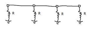
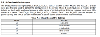
According to the DS320PR810 datasheet, the device has eight 5-level input pins that are used to control the configuration of the device.

It seems like the input level is decided by the connected resistor values as specified by the below table.

When I reviewed the DS320PR810_RSC_EVM_Schematics.pdf, I found that the resistor values were not matching with the table.

Please explain to me why the schematic was designed with the different values of resistors.

Please let me ask you a couple of more questions on the device.

There are several configuration/operation modes(Pin mode, SMBus Primary/Secondary mode) for the device. 

  1. Is the pin mode sufficient to make the device operate? Or is SMBus configuration a must?
  2. If the pin mode is sufficient, I don't need the eeprom, right?

"

  • Hi Samuel,

    Please explain to me why the schematic was designed with the different values of resistors.

    The DS320PR810 EVM has four different devices on it to provide a x16 link width. For convenience, some pins such as MODE are shared between all devices on the board - in the example of MODE, it would be too complicated to have some devices in Pin Mode and other devices in I2C primary mode, so we expect all of them to be in the same operating mode at any given time. However on our EVM we do not want to change four different MODE jumpers when they should all have the same setting, so we can connect the pin nodes to each other. The equivalent circuit then becomes this:

    And we can simplify the four identical resistor straps in parallel to become R/4:

    In the example screenshot, the L0 setting is 249 Ohms = 1k Ohms / 4, the L1 setting is 2.05k Ohms = 8.2k  Ohms / 4, etc., essentially we take the normal strap setting and divide it by 4.

    So if your end application is a experiment board with multiple devices similar to our EVM, it could make sense to share configuration pins this way, but in most applications you will want to configure devices with individual, non-shared straps, and then you can follow the normal settings in the table.

    Is the pin mode sufficient to make the device operate? Or is SMBus configuration a must?

    The device can be operated completely in Pin Mode. SMBus/I2C is more convenient for tuning and debugging but it's not required.

    If the pin mode is sufficient, I don't need the eeprom, right?

    Yes. EEPROM is only required for the SMBus/I2C Primary mode, even the other I2C mode does not need EEPROM.

    Best,

    Evan Su

  • Hi Evan,

    I understood the explanation on R/4 for the Mode pin.

    There is one more strange resistor value used for GAIN_US/DS.

    What is the reason J21 1&2 is R/4 and others are R/2?

    Regards,

    Samuel

  • Hi Samuel,

    This jumper is intended to control two devices so R/2 should be the correct division ratio. I am not sure of the reason for the division ratio being R/4 for the L0 setting. It is possible that the EVM designers were not able to find and use a 500 Ohm resistor for some reason and 249 Ohms could still be identified by the internal comparator as L0, but that is just a guess. I recommend following the correct division ratios in customer designs.

    Best,

    Evan Su

  • Hi Evan,

    Thanks for your explanation.

    If I set J24(1&2) and J26(1&2), it will make R/4 is the correct value.

    Is my understanding correct?

    Regards,

    Samuel

  • Hi Samuel,

    J24 and J26 are simple connection jumpers with no resistor shunts. Setting them both to 1&2 will connect the US1 and US2 devices to a common GAIN_US node controlled by J21.

    Since GAIN_US is shared between two devices, ideally the division ratio should be R/2.

    Best,

    Evan Su

  • Hi Evan,

    It is correct that GAIN_US is shared between two devices but each device has two pins(GAIN0 and GAIN1) are connected to GAIN_US.

    In such case, I think it should be R/4.

    Did I miss something?

    Regards,

    Samuel

  • Hi Samuel,

    Good observation, I understand what you mean now. In pin mode there would be a total of 4 pins across 2 devices controlled by J21, so I would expect R/4 to be the correct division ratio in that case. In the I2C modes, only 2 pins are connected, but they are also unused so the shunt resistance applied should not matter.

    I will take a look at the physical EVM to investigate the issue further.

    Best,

    Evan Su