This thread has been locked.

If you have a related question, please click the "Ask a related question" button in the top right corner. The newly created question will be automatically linked to this question.

TCA9534: Unable to Drive the IO Expander TCA9534PWR from microcontroller TM4C1294ncpdt using I2C4

Part Number: TCA9534
Other Parts Discussed in Thread: TM4C1294NCPDT,

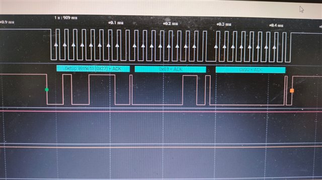
Unable to Drive the IO Expander TCA9534PWR from microcontroller TM4C1294ncpdt using I2C4. I have Initialised the I2C4 and am trying to configure the Io expander TCA9534 as output. But somehow succeeded in configuring the chip. Here is the Snapshot of the I2C configuration (address 0x27, config register 0x03 and writing data value 0x00 for all output).
And also followed by the source code which i have used in current project to drive the io expander. void I2c_init() { //#######INITIALIZATION############ // The I2C3 peripheral must be enabled before use. SysCtlPeripheralEnable(SYSCTL_PERIPH_I2C3); SysCtlPeripheralReset(SYSCTL_PERIPH_I2C3); // The I2C4 peripheral must be enabled before use. SysCtlPeripheralEnable(SYSCTL_PERIPH_I2C4); SysCtlPeripheralReset(SYSCTL_PERIPH_I2C4); SysCtlPeripheralEnable(SYSCTL_PERIPH_GPIOK); GPIOPinConfigure(GPIO_PK4_I2C3SCL); GPIOPinConfigure(GPIO_PK5_I2C3SDA); GPIOPinTypeI2CSCL(GPIO_PORTK_BASE, GPIO_PIN_4); GPIOPinTypeI2C(GPIO_PORTK_BASE, GPIO_PIN_5); I2CMasterInitExpClk(I2C3_BASE, g_ui32SysClock, false); // I2CMasterSlaveAddrSet(I2C3_BASE, SLAVE_ADDRESS , false); // slave address to 0x20 I2CMasterEnable(I2C3_BASE); GPIOPinConfigure(GPIO_PK6_I2C4SCL); GPIOPinConfigure(GPIO_PK7_I2C4SDA); GPIOPinTypeI2CSCL(GPIO_PORTK_BASE, GPIO_PIN_6); GPIOPinTypeI2C(GPIO_PORTK_BASE, GPIO_PIN_7); I2CMasterInitExpClk(I2C4_BASE, g_ui32SysClock, false); I2CMasterSlaveAddrSet(I2C4_BASE, 0x27 , false); // slave address to 0x27 I2CMasterEnable(I2C4_BASE); I2CMasterGlitchFilterConfigSet(I2C3_BASE, I2C_MASTER_GLITCH_FILTER_2); I2CMasterGlitchFilterConfigSet(I2C4_BASE, I2C_MASTER_GLITCH_FILTER_2); } void I2CSend4(uint8_t slave_addr, uint8_t num_of_args, ...) { uint8_t i =0; // Tell the master module what address it will place on the bus when // communicating with the slave. I2CMasterSlaveAddrSet(I2C4_BASE, slave_addr, false); //stores list of variable number of arguments va_list vargs; //specifies the va_list to "open" and the last fixed argument //so vargs knows where to start looking va_start(vargs, num_of_args); //put data to be sent into FIFO I2CMasterDataPut(I2C4_BASE, va_arg(vargs, uint32_t)); //if there is only one argument, we only need to use the //single send I2C function if(num_of_args == 1) { //Initiate send of data from the MCU I2CMasterControl(I2C4_BASE, I2C_MASTER_CMD_SINGLE_SEND); // Wait until MCU is done transferring. while(I2CMasterBusy(I2C4_BASE)); //"close" variable argument list va_end(vargs); } //otherwise, we start transmission of multiple bytes on the //I2C bus else { //Initiate send of data from the MCU I2CMasterControl(I2C4_BASE, I2C_MASTER_CMD_BURST_SEND_START); // Wait until MCU is done transferring. while(I2CMasterBusy(I2C4_BASE)); //send num_of_args-2 pieces of data, using the //BURST_SEND_CONT command of the I2C module for( i = 1; i < (num_of_args - 1); i++) { //put next piece of data into I2C FIFO I2CMasterDataPut(I2C4_BASE, va_arg(vargs, uint32_t)); //send next data that was just placed into FIFO I2CMasterControl(I2C4_BASE, I2C_MASTER_CMD_BURST_SEND_CONT); // Wait until MCU is done transferring. while(I2CMasterBusy(I2C4_BASE)); } //put last piece of data into I2C FIFO I2CMasterDataPut(I2C4_BASE, va_arg(vargs, uint32_t)); //send next data that was just placed into FIFO I2CMasterControl(I2C4_BASE, I2C_MASTER_CMD_BURST_SEND_FINISH); // Wait until MCU is done transferring. while(I2CMasterBusy(I2C4_BASE)); //"close" variable args list va_end(vargs); } } //read specified register on slave device uint32_t I2CReceive4(uint32_t slave_addr, uint8_t reg) { //specify that we are writing (a register address) to the //slave device I2CMasterSlaveAddrSet(I2C4_BASE, slave_addr, false); //specify register to be read I2CMasterDataPut(I2C4_BASE, reg); //send control byte and register address byte to slave device I2CMasterControl(I2C4_BASE, I2C_MASTER_CMD_BURST_SEND_START); //wait for MCU to finish transaction while(I2CMasterBusy(I2C4_BASE)); //specify that we are going to read from slave device I2CMasterSlaveAddrSet(I2C4_BASE, slave_addr, true); //send control byte and read from the register we //specified I2CMasterControl(I2C4_BASE, I2C_MASTER_CMD_SINGLE_RECEIVE); //wait for MCU to finish transaction while(I2CMasterBusy(I2C4_BASE)); //return data pulled from the specified register return I2CMasterDataGet(I2C4_BASE); } void Set_output() { I2CSend4(SLAVE_DR1, 2, 0x03, 0x00); } void Write_output(uint8_t pin) { I2CSend4(SLAVE_DR1,2, 0x01, pin); }

  • void I2c_init()
    {
        //#######INITIALIZATION############
    
                // The I2C3 peripheral must be enabled before use.
                SysCtlPeripheralEnable(SYSCTL_PERIPH_I2C3);
                SysCtlPeripheralReset(SYSCTL_PERIPH_I2C3);
    
                // The I2C4 peripheral must be enabled before use.
                SysCtlPeripheralEnable(SYSCTL_PERIPH_I2C4);
                SysCtlPeripheralReset(SYSCTL_PERIPH_I2C4);
    
                SysCtlPeripheralEnable(SYSCTL_PERIPH_GPIOK);
    
                GPIOPinConfigure(GPIO_PK4_I2C3SCL);
                GPIOPinConfigure(GPIO_PK5_I2C3SDA);
    
                GPIOPinTypeI2CSCL(GPIO_PORTK_BASE, GPIO_PIN_4);
                GPIOPinTypeI2C(GPIO_PORTK_BASE, GPIO_PIN_5);
                I2CMasterInitExpClk(I2C3_BASE, g_ui32SysClock, false);
               // I2CMasterSlaveAddrSet(I2C3_BASE, SLAVE_ADDRESS , false); // slave address to 0x20
                I2CMasterEnable(I2C3_BASE);


                GPIOPinConfigure(GPIO_PK6_I2C4SCL);
                GPIOPinConfigure(GPIO_PK7_I2C4SDA);
    
                GPIOPinTypeI2CSCL(GPIO_PORTK_BASE, GPIO_PIN_6);
                GPIOPinTypeI2C(GPIO_PORTK_BASE, GPIO_PIN_7);
                I2CMasterInitExpClk(I2C4_BASE, g_ui32SysClock, false);
                I2CMasterSlaveAddrSet(I2C4_BASE, 0x27 , false); // slave address to 0x27
                I2CMasterEnable(I2C4_BASE);
    
                I2CMasterGlitchFilterConfigSet(I2C3_BASE, I2C_MASTER_GLITCH_FILTER_2);
                I2CMasterGlitchFilterConfigSet(I2C4_BASE, I2C_MASTER_GLITCH_FILTER_2);
    
          }
    
    void I2CSend4(uint8_t slave_addr, uint8_t num_of_args, ...)
    {
        uint8_t i =0;
        // Tell the master module what address it will place on the bus when
        // communicating with the slave.
        I2CMasterSlaveAddrSet(I2C4_BASE, slave_addr, false);
    
        //stores list of variable number of arguments
        va_list vargs;
    
        //specifies the va_list to "open" and the last fixed argument
        //so vargs knows where to start looking
        va_start(vargs, num_of_args);
    
        //put data to be sent into FIFO
        I2CMasterDataPut(I2C4_BASE, va_arg(vargs, uint32_t));
    
        //if there is only one argument, we only need to use the
        //single send I2C function
        if(num_of_args == 1)
        {
            //Initiate send of data from the MCU
            I2CMasterControl(I2C4_BASE, I2C_MASTER_CMD_SINGLE_SEND);
    
            // Wait until MCU is done transferring.
            while(I2CMasterBusy(I2C4_BASE));
    
            //"close" variable argument list
            va_end(vargs);
        }
    
        //otherwise, we start transmission of multiple bytes on the
        //I2C bus
        else
        {
            //Initiate send of data from the MCU
            I2CMasterControl(I2C4_BASE, I2C_MASTER_CMD_BURST_SEND_START);
    
            // Wait until MCU is done transferring.
            while(I2CMasterBusy(I2C4_BASE));
    
            //send num_of_args-2 pieces of data, using the
            //BURST_SEND_CONT command of the I2C module
            for( i = 1; i < (num_of_args - 1); i++)
            {
                //put next piece of data into I2C FIFO
                I2CMasterDataPut(I2C4_BASE, va_arg(vargs, uint32_t));
                //send next data that was just placed into FIFO
                I2CMasterControl(I2C4_BASE, I2C_MASTER_CMD_BURST_SEND_CONT);
    
                // Wait until MCU is done transferring.
                while(I2CMasterBusy(I2C4_BASE));
            }
    
            //put last piece of data into I2C FIFO
            I2CMasterDataPut(I2C4_BASE, va_arg(vargs, uint32_t));
            //send next data that was just placed into FIFO
            I2CMasterControl(I2C4_BASE, I2C_MASTER_CMD_BURST_SEND_FINISH);
            // Wait until MCU is done transferring.
            while(I2CMasterBusy(I2C4_BASE));
    
            //"close" variable args list
            va_end(vargs);
        }
    }
    //read specified register on slave device
    uint32_t I2CReceive4(uint32_t slave_addr, uint8_t reg)
    {
        //specify that we are writing (a register address) to the
        //slave device
        I2CMasterSlaveAddrSet(I2C4_BASE, slave_addr, false);
    
        //specify register to be read
        I2CMasterDataPut(I2C4_BASE, reg);
    
        //send control byte and register address byte to slave device
        I2CMasterControl(I2C4_BASE, I2C_MASTER_CMD_BURST_SEND_START);
    
        //wait for MCU to finish transaction
        while(I2CMasterBusy(I2C4_BASE));
    
        //specify that we are going to read from slave device
        I2CMasterSlaveAddrSet(I2C4_BASE, slave_addr, true);
    
        //send control byte and read from the register we
        //specified
        I2CMasterControl(I2C4_BASE, I2C_MASTER_CMD_SINGLE_RECEIVE);
    
        //wait for MCU to finish transaction
        while(I2CMasterBusy(I2C4_BASE));
    
        //return data pulled from the specified register
        return I2CMasterDataGet(I2C4_BASE);
    }
    
    void Set_output()
    {
       I2CSend4(SLAVE_DR1, 2, 0x03, 0x00); 
    }
    
    void Write_output(uint8_t pin)
    {
       I2CSend4(SLAVE_DR1,2, 0x01, pin);
    }

  • These I²C waveforms look OK.

    What is the problem that you're seeing?

  • Hi Ramesh,

    You write to the configuration register to set all p-ports to outputs, but do you write to the output port register as well to toggle between high and low logic levels? 

    Regards,

    Tyler

  • We have been able to resolve the issue. 1. Proper register allocations 2. We trimmed the overall code to reduce memory size.