This thread has been locked.

If you have a related question, please click the "Ask a related question" button in the top right corner. The newly created question will be automatically linked to this question.

PCA9548A: Interference between channels--test channel SC2/SD2 and SC3/SD3 channels of U15

Part Number: PCA9548A

36. I2C Switch.pdf45. VDD_3V3.pdf

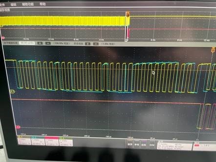
1. When we frequently access the two channels of PCA9548APWR through I2C, when accessing the two channels, the three channels will be opened with probability, and the waveform is shown in the following figure,

The yellow and blue waveforms above measure the front-end I2C signal of PCA9548APWR, while the red and green waveforms below measure the 3-channel back-end I2C signal of PCA9548APWR. From the waveform, it can be seen that the instruction we sent to PCA9548APWR (address 0x71) is to open 2 channels. May I ask why 3 channels were opened?
2. In addition, we simultaneously tested the backend signals of channels 2 and 3 of PCA9548APWR and found that channels 2 and 3 can be opened simultaneously at certain times. Is this situation caused by frequent operations on PCA9548APWR?
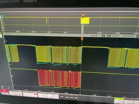
  • The first image shows three bytes being written. The first byte (11100010) is the address and R/W byte, and is correct. The second byte (00000100) activates the third channel. The third byte (01111111) activates the first seven channels.

    Why is your controller sending that third byte?

  • Hi Zhang,

    The I2C switches portfolio has now moved to the MUX team. I have changed the responsible org. They should get back to you within 24 hours. 

    Regards,

    Tyler

  • Zhang,

    As Clemen's pointed out, you are sending 3 bytes to our device. Our device only requires 2 bytes (the address|RnW-bit and the second byte to select/enable the channel) after the two bytes are sent, you should immediately issue a stop condition (this is important, it cannot be a restart condition).

    -Bobby