This thread has been locked.

If you have a related question, please click the "Ask a related question" button in the top right corner. The newly created question will be automatically linked to this question.

DS90UB941AS-Q1: no video output

Part Number: DS90UB941AS-Q1

hi team,

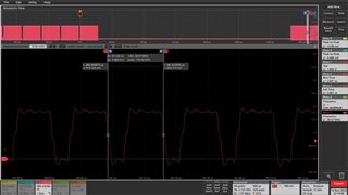
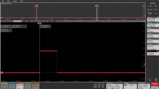
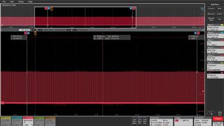
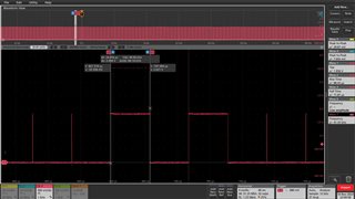
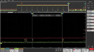
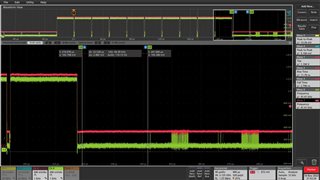
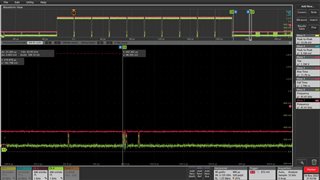
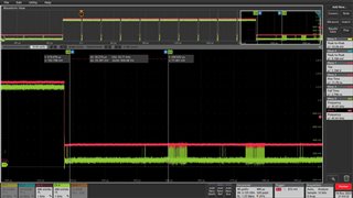
my customer use 941 pair with 928 and 926, now 926 can work normal, but 928 can't work normal, no video output.

back ground: the lock is no problem , I2C can work normal with 928, GPIO pass through can work normal

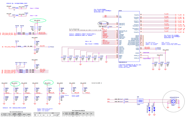
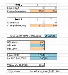
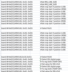
the 941 script config is as follow:

https://e2e.ti.com/cfs-file/__key/communityserver-discussions-components-files/138/config_5F00_new_5F00_hud

could you help check the problem?

  • Hi Colt,

    Are both the 928 and 926 programmed to enable the LVCMOS output via register 0x02 after startup? Can you give more information on the customer's system?

    Best,

    Jack

  • Hi Jack:

         1. LVCMOS has been configured;

         2. HQX platform, 941's DSI_VC_DTYPE is 0x3E, link lock is ok;

         3. Pattern test doesn't work.;

    i2cdbgr -D /dev/i2c3 -s 0x31 -w -b 2 -o 0x39 -x 0x02
    i2cdbgr -D /dev/i2c3 -s 0x31 -w -b 2 -o 0x65 -x 0x0c
    i2cdbgr -D /dev/i2c3 -s 0x31 -w -b 2 -o 0x64 -x 0x11

         4. This LCD is ok on other platform, 927->928 design;

  • hi jack,

    add the more information, 941 use super frame pair with 926 and 928, 926 is for cluster , 928 is for HUD.

    the follow is the 928 schematic and video timing .

    the follow is the video timing of 926

  • Hi Colt and Chen,

    Let's focus on getting patgen up first on the system. 

    What type of super frame (alternate line, alternate pixel, etc.) is being sent in and how are the 928 and 926 connected to the 941AS (splitter mode, independent 2:2 mode)?

       3. Pattern test doesn't work.;

    i2cdbgr -D /dev/i2c3 -s 0x31 -w -b 2 -o 0x39 -x 0x02
    i2cdbgr -D /dev/i2c3 -s 0x31 -w -b 2 -o 0x65 -x 0x0c
    i2cdbgr -D /dev/i2c3 -s 0x31 -w -b 2 -o 0x64 -x 0x11

    What's the full code for 928 pattern gen? And what port on the 941AS is connected to the 928?

    Best,

    Jack

  • Hi Jack:

         941 Dout0 -> 926

         941 Dout1 -> 928

         Splitter mode,

         Just three  test cmds.

        -----

    What type of super frame (alternate line, alternate pixel, etc.)

    ---Should be alternate pixel, Bit[7] of 941's 0x56 register is setted.

    More info:

    1.  Dout1 work normal when connect 926 lcd before on this project.   

    2.  The 928 lcd work normal when used other platform.

    3.  Single mode still doesn't work.

    4. Attempting to configure two identical 928 LCD displays connected with DOUT0 and DOUT1, did not work.

  • Hi Chen,

    Thank you for the information on this system and for the background info.

    Because the link is there for both the 926 and the 928, there is a timing issue causing the 928 to not output video. I will be sending a script to run the patgen on the 941as to verify that the video path has no issues. Once we get the patgen working, we can fix the superframe input issue.

    There is an app note for 941AS splitter mode operations. I'll attach it if you haven't come across it yet.

    Link

    Best,

    Jack

  • Hi Chen,

    Try this 941 patgen script. It will output on Port 1 for the 928.

    #941 patgen on port 1
    
    serAddr = 0x34
    
    board.WriteI2C(serAddr, 0x01, 0x08) #Disable DSI
    board.WriteI2C(serAddr, 0x1E, 0x1) #Enable port 1 I2C writes
    board.WriteI2C(serAddr, 0x5B, 0x07) #Force splitter mode
    
    #Patgen setup for (1280 * 640 @ 60 fps)
    
    board.WriteI2C(serAddr, 0x66, 0x03) # N divider
    board.WriteI2C(serAddr, 0x67, 0x2D)
    
    board.WriteI2C(serAddr, 0x66, 0x04)
    board.WriteI2C(serAddr, 0x67, 0x5F)
    
    board.WriteI2C(serAddr, 0x66, 0x05)
    board.WriteI2C(serAddr, 0x67, 0xA5)
    
    board.WriteI2C(serAddr, 0x66, 0x06)
    board.WriteI2C(serAddr, 0x67, 0x28)
    
    board.WriteI2C(serAddr, 0x66, 0x07)
    board.WriteI2C(serAddr, 0x67, 0x00)
    
    board.WriteI2C(serAddr, 0x66, 0x08)
    board.WriteI2C(serAddr, 0x67, 0x05)
    
    board.WriteI2C(serAddr, 0x66, 0x09)
    board.WriteI2C(serAddr, 0x67, 0x28)
    
    board.WriteI2C(serAddr, 0x66, 0x0A)
    board.WriteI2C(serAddr, 0x67, 0x0A)
    
    board.WriteI2C(serAddr, 0x66, 0x0B)
    board.WriteI2C(serAddr, 0x67, 0x02)
    
    board.WriteI2C(serAddr, 0x66, 0x0C)
    board.WriteI2C(serAddr, 0x67, 0x28)
    
    board.WriteI2C(serAddr, 0x66, 0x0D)
    board.WriteI2C(serAddr, 0x67, 0x04)
    
    board.WriteI2C(serAddr, 0x66, 0x0E)
    board.WriteI2C(serAddr, 0x67, 0x03)
    
    board.WriteI2C(serAddr, 0x66, 0x1A) #M divider
    board.WriteI2C(serAddr, 0x67, 0x03)
    
    #Enable patgen
    board.WriteI2C(serAddr, 0x65, 0x4) #Patgen use its own video timing
    board.WriteI2C(serAddr, 0x64, 0x1) #Enable patgen


    Best,

    Jack

  • Thanks, Jack.

    Because 928's pattern isn't ok,  we've tried 941 pattern  last day and it works fine. 

    Since both DOUT0 and DOUT1(when used  926 lcd before) have been working properly,  it's more like timing issue, right? We can't catch the 941's input wave , please provide some suggestions, thanks.

    ---------------

    recent info:

    1. used pattern:

    i2cdbgr -D /dev/i2c3 -s 0x1b -w -b 2 -o 0x67 -x 0x2d
    i2cdbgr -D /dev/i2c3 -s 0x1b -w -b 2 -o 0x66 -x 0x04
    i2cdbgr -D /dev/i2c3 -s 0x1b -w -b 2 -o 0x67 -x 0x5f
    i2cdbgr -D /dev/i2c3 -s 0x1b -w -b 2 -o 0x66 -x 0x05
    i2cdbgr -D /dev/i2c3 -s 0x1b -w -b 2 -o 0x67 -x 0xE5
    i2cdbgr -D /dev/i2c3 -s 0x1b -w -b 2 -o 0x66 -x 0x06
    i2cdbgr -D /dev/i2c3 -s 0x1b -w -b 2 -o 0x67 -x 0x28
    i2cdbgr -D /dev/i2c3 -s 0x1b -w -b 2 -o 0x66 -x 0x07
    i2cdbgr -D /dev/i2c3 -s 0x1b -w -b 2 -o 0x67 -x 0x00
    i2cdbgr -D /dev/i2c3 -s 0x1b -w -b 2 -o 0x66 -x 0x08
    i2cdbgr -D /dev/i2c3 -s 0x1b -w -b 2 -o 0x67 -x 0x05
    i2cdbgr -D /dev/i2c3 -s 0x1b -w -b 2 -o 0x66 -x 0x09
    i2cdbgr -D /dev/i2c3 -s 0x1b -w -b 2 -o 0x67 -x 0x28
    i2cdbgr -D /dev/i2c3 -s 0x1b -w -b 2 -o 0x66 -x 0x0a
    i2cdbgr -D /dev/i2c3 -s 0x1b -w -b 2 -o 0x67 -x 0x08
    i2cdbgr -D /dev/i2c3 -s 0x1b -w -b 2 -o 0x66 -x 0x0b
    i2cdbgr -D /dev/i2c3 -s 0x1b -w -b 2 -o 0x67 -x 0x04
    i2cdbgr -D /dev/i2c3 -s 0x1b -w -b 2 -o 0x66 -x 0x0c
    i2cdbgr -D /dev/i2c3 -s 0x1b -w -b 2 -o 0x67 -x 0x10
    i2cdbgr -D /dev/i2c3 -s 0x1b -w -b 2 -o 0x66 -x 0x0d
    i2cdbgr -D /dev/i2c3 -s 0x1b -w -b 2 -o 0x67 -x 0x05
    i2cdbgr -D /dev/i2c3 -s 0x1b -w -b 2 -o 0x66 -x 0x0e
    i2cdbgr -D /dev/i2c3 -s 0x1b -w -b 2 -o 0x67 -x 0x03
    i2cdbgr -D /dev/i2c3 -s 0x1b -w -b 2 -o 0x66 -x 0x1a
    i2cdbgr -D /dev/i2c3 -s 0x1b -w -b 2 -o 0x67 -x 0x03
    i2cdbgr -D /dev/i2c3 -s 0x1b -w -b 2 -o 0x65 -x 0x4
    i2cdbgr -D /dev/i2c3 -s 0x1b -w -b 2 -o 0x64 -x 0x5

    2.  DSI0 input,
    DSI_Video_TrafficMode_NonBurst_VSPulse

    3. For checking issue and avoiding different lcd parameters affects, we configured both DOUT0 and DOUT1 are connected to 928 lcds with the same parameters.

    4. 941's configuration(tskip_cnt test the 0x2e parameters also, after adding the vfp/vbp/hfp/hbp, etc):

  • Hi:

      now ,we use 941 to 928 (HUD) single link ,  the hud can output pattern from 941,but can not output image from 8155 board, please help us to analyse,

    now ,we use the following env,

    1、 DSI_Video_TrafficMode_NonBurst_VSPulse is enable

    2、the configs as follows: 

          uVisWidth        = '1280'
          uHsyncFrontPorch = '45'
          uHsyncWidth      = '10'
          uHsyncBackPorch  = '40'
          uVisHeight       = '680'
          uVsyncFrontPorch = '4'                                                                                                                                                                  
          uVsyncWidth      = '2'
          uVsyncBackPorch  = '4'
          uPixelFreqInHz   = '56925000'

    3 、 dump 941 register result as follows:

         0  1  2  3  4  5  6  7  8  9  a  b  c  d  e  f    0123456789abcdef
    00: 34 00 00 9a 00 00 58 00 00 01 43 16 67 30 00 00    4..?..X..?C?g0..
    10: 00 00 00 af 00 00 fe 9e 7f 7f 01 00 00 00 01 00    ...?..?????...?.
    20: 03 00 25 00 b6 00 00 00 01 20 20 b8 00 00 a5 5a    ?.%.?...?  ?..?Z
    30: c0 09 00 05 0c 00 00 00 00 00 00 00 00 00 81 02    ??.??.........??
    40: 04 05 02 00 00 00 00 00 00 00 00 00 00 00 00 8c    ???............?
    50: 16 00 00 00 02 10 00 02 00 00 d9 81 07 06 44 38    ?...??.?..????D8
    60: 22 02 00 00 10 00 00 00 00 00 00 00 00 02 20 00    "?..?........? .
    70: 00 00 00 00 00 00 00 00 00 00 00 00 00 00 78 00    ..............x.
    80: 00 00 00 00 00 00 00 00 00 00 00 00 00 00 00 00    ................
    90: 00 00 00 00 00 00 00 00 00 00 00 00 00 00 00 00    ................
    a0: 00 00 00 00 00 00 00 00 00 00 00 00 00 00 00 00    ................
    b0: 00 00 00 00 00 00 00 00 00 00 00 00 00 00 00 00    ................
    c0: 00 00 82 00 68 00 00 44 40 00 00 00 00 02 ff 00    ..?.h..D@....??.
    d0: 00 00 00 00 00 00 00 00 00 00 00 00 00 00 00 00    ................
    e0: 00 00 82 00 68 08 00 00 00 00 00 00 00 02 00 00    ..?.h?.......?..
    f0: 5f 55 42 39 34 31 00 00 00 00 00 00 00 00 00 00    _UB941..........
    

    4 、we test the 941 pin -- GPIO 14 ,38 、39 and line0,please help us to analyse the picture from those pins, 

    GPIO 14 picture


    pin 38 and 39 picture


    Line0 picture


  • hi Jack,

    add the correct,

    customer use the Non Burst with SYNC Pulse

  • Hi Colt and Chen,

    Thank you for confirming that the 941 patgen with internal timing and internal clock works successfully. From the images you sent over, I can see that the SoC is entering LP-11 every frame so that is not an issue.

    it's more like timing issue, right?

    Yes, this is most likely a timing issue. For alternate pixel superframe, the incoming video frame must consist of two identical size images. Because the downstream displays are not of equal size, was the SoC adding padding to the incoming images?

    Since we can get 941 patgen working with internal timing and internal clock, let's check that external clock and external timing will work for the patgen.

    Use the below script to enable 941 patgen with internal timing and external clock. If the script works then the DSI clock is working as expected.

    #941 patgen on port 1
    
    serAddr = 0x34
    
    board.WriteI2C(serAddr, 0x01, 0x08) #Disable DSI
    board.WriteI2C(serAddr, 0x1E, 0x1) #Enable port 1 I2C writes
    board.WriteI2C(serAddr, 0x5B, 0x07) #Force splitter mode
    
    #Patgen setup for (1280 * 640 @ 60 fps)
    
    board.WriteI2C(serAddr, 0x66, 0x03) # N divider
    board.WriteI2C(serAddr, 0x67, 0x2D)
    
    board.WriteI2C(serAddr, 0x66, 0x04)
    board.WriteI2C(serAddr, 0x67, 0x5F)
    
    board.WriteI2C(serAddr, 0x66, 0x05)
    board.WriteI2C(serAddr, 0x67, 0xA5)
    
    board.WriteI2C(serAddr, 0x66, 0x06)
    board.WriteI2C(serAddr, 0x67, 0x28)
    
    board.WriteI2C(serAddr, 0x66, 0x07)
    board.WriteI2C(serAddr, 0x67, 0x00)
    
    board.WriteI2C(serAddr, 0x66, 0x08)
    board.WriteI2C(serAddr, 0x67, 0x05)
    
    board.WriteI2C(serAddr, 0x66, 0x09)
    board.WriteI2C(serAddr, 0x67, 0x28)
    
    board.WriteI2C(serAddr, 0x66, 0x0A)
    board.WriteI2C(serAddr, 0x67, 0x0A)
    
    board.WriteI2C(serAddr, 0x66, 0x0B)
    board.WriteI2C(serAddr, 0x67, 0x02)
    
    board.WriteI2C(serAddr, 0x66, 0x0C)
    board.WriteI2C(serAddr, 0x67, 0x28)
    
    board.WriteI2C(serAddr, 0x66, 0x0D)
    board.WriteI2C(serAddr, 0x67, 0x04)
    
    board.WriteI2C(serAddr, 0x66, 0x0E)
    board.WriteI2C(serAddr, 0x67, 0x03)
    
    board.WriteI2C(serAddr, 0x66, 0x1A) #M divider
    board.WriteI2C(serAddr, 0x67, 0x03)
    
    #Enable patgen
    board.WriteI2C(serAddr, 0x65, 0x0) #Patgen using external timing and clock
    board.WriteI2C(serAddr, 0x64, 0x1) #Enable patgen


    Use the below script to enable 941 patgen with external timing and external clock. If the script works then the DSI input is working as expected.

    #941 patgen on port 1
    
    serAddr = 0x34
    
    board.WriteI2C(serAddr, 0x01, 0x08) #Disable DSI
    board.WriteI2C(serAddr, 0x1E, 0x1) #Enable port 1 I2C writes
    board.WriteI2C(serAddr, 0x5B, 0x07) #Force splitter mode
    
    #Patgen setup for (1280 * 640 @ 60 fps)
    
    board.WriteI2C(serAddr, 0x66, 0x03) # N divider
    board.WriteI2C(serAddr, 0x67, 0x2D)
    
    board.WriteI2C(serAddr, 0x66, 0x04)
    board.WriteI2C(serAddr, 0x67, 0x5F)
    
    board.WriteI2C(serAddr, 0x66, 0x05)
    board.WriteI2C(serAddr, 0x67, 0xA5)
    
    board.WriteI2C(serAddr, 0x66, 0x06)
    board.WriteI2C(serAddr, 0x67, 0x28)
    
    board.WriteI2C(serAddr, 0x66, 0x07)
    board.WriteI2C(serAddr, 0x67, 0x00)
    
    board.WriteI2C(serAddr, 0x66, 0x08)
    board.WriteI2C(serAddr, 0x67, 0x05)
    
    board.WriteI2C(serAddr, 0x66, 0x09)
    board.WriteI2C(serAddr, 0x67, 0x28)
    
    board.WriteI2C(serAddr, 0x66, 0x0A)
    board.WriteI2C(serAddr, 0x67, 0x0A)
    
    board.WriteI2C(serAddr, 0x66, 0x0B)
    board.WriteI2C(serAddr, 0x67, 0x02)
    
    board.WriteI2C(serAddr, 0x66, 0x0C)
    board.WriteI2C(serAddr, 0x67, 0x28)
    
    board.WriteI2C(serAddr, 0x66, 0x0D)
    board.WriteI2C(serAddr, 0x67, 0x04)
    
    board.WriteI2C(serAddr, 0x66, 0x0E)
    board.WriteI2C(serAddr, 0x67, 0x03)
    
    board.WriteI2C(serAddr, 0x66, 0x1A) #M divider
    board.WriteI2C(serAddr, 0x67, 0x03)
    
    #Enable patgen
    board.WriteI2C(serAddr, 0x65, 0x0) #Patgen using external timing and clock
    board.WriteI2C(serAddr, 0x64, 0x1) #Enable patgen


    Best,

    Jack

  • Hi Colt and Chen,

    Please also refer to this app note for issues with debugging 941 DSI input.

    www.ti.com/.../ds90ub941as-q1.pdf

    Best,

    Jack

  • Hi ,

      now ,please help us to confirm 941 whether can support the 926 cluster and 928 hud can output the required pictures in splitter mode, the cluster and hud  timimg as following:    

  • Hi Chen,

    I have two concerns with the 941's ability to support this system. The first concern I have with the video timings is that the 928 hud display is set for negative sync polarity ("low pulse width") while the 926 cluster display does not use negative sync polarity. Can you confirm if this is correct? Both displays will need to have the same sync polarity for splitter mode operation.

    The second concern is that the 926 cluster display will not support the additional vertical blanking introduced by the superframe. For the incoming superframe, the 926 vertical timing will have to be padded beyond the 394 max lines indicated in the timing field. This will violate the max PCLK setting.

    941 whether can support the 926 cluster and 928 hud can output the required pictures in splitter mode

    Due to the reasons mentioned above, the 941 cannot support these video timings in splitter mode. My recommendation is to use Independent 2:2 Mode for this system as it does not require identical video timings for the deserializers.

    Best,

    Jack